Blog
Pi1541 Build
If you’re into retro-computing and have a Commodore 8-bit computer, such as the Commodore 64 or Commodore 128, you’re going to love this project! We’re going to do a Pi1541 build.
The Commodore line of 8-bit computers used a disk drive called the Commodore 1541 (later the 1571 and 1581). This venerable drive is a classic and deserves to be treated us such. However, it’s also not all that reliable these days as its age is catching up to the components. In fact, many of the Commodore 1541’s components are no longer available at all. For this reason, I try to use mine as little as possible and keep it as more of a showpiece in my museum.
Why Choose the Pi1541?
There are other drive emulators out there. In fact we wrote the SD2IEC Manual (Unofficial Manual) a couple of years ago, a very popular page on our site. The SD2IEC is simple “emulator” that allows you to read and write SD cards on the C64. I put emulator in quotes, because the SD2IEC is not a true emulator, rather it emulates some functions of the 1541 based on commands passed to it. This can be a problem, since anything that attempts to change code in the 1541 will fail to work. This means many copy protection schemes, fastloaders, and other such utilities are simple not going to function on the SD2IEC devices.
The Pi1541 is a Real 1541 Emulator
The Pi1541 on the other hand is a true Commodore 1541 emulator! It uses a copy of the original ROM images from the Commodore 1541 and a full 6502 emulator to present itself to the computer as a true drive in every way. Due to this, everything works with 100% compatibility, including all fastloader routines, copy protection systems, and the like. It just works. In fact, it works with the EPYX fastloader cartridge also, one of my favorite C64 fastloaders!
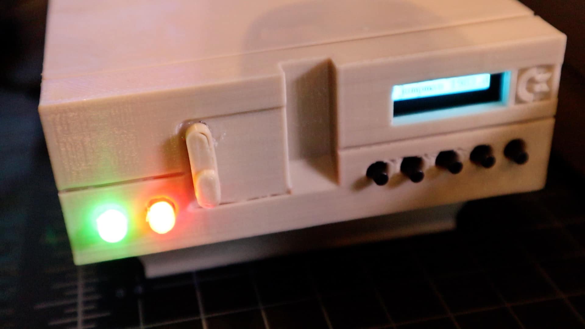
In addition to being a full emulator, it has a hardware LED, and piezo buzzer to provide the sights and sounds of the drive working, along with an OLED screen for browsing SD card images. Oh! Did I mention you can 3D print some awesome retro cases to put it in?
So today, we’re going to build a Pi1541!
Building a Pi1541
Let’s begin the process of building our Pi1541. First let’s make sure you have all of the parts you need to get started. Here’s a handy Pi1541 parts list to get you started:
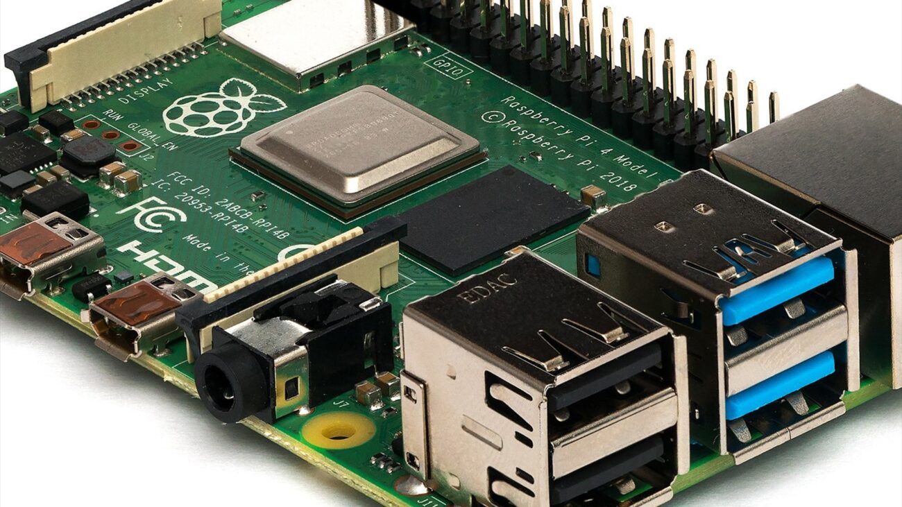
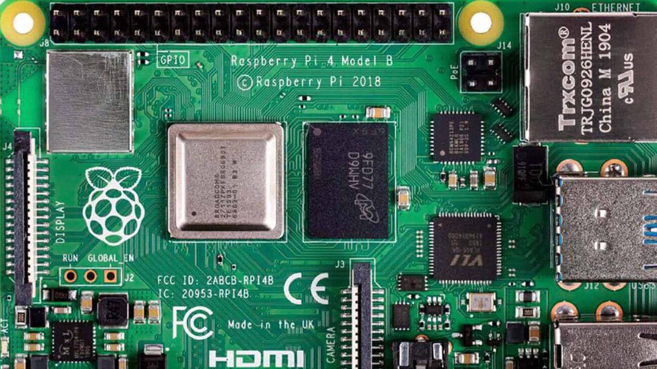
- Raspberry Pi 3
- Raspberry Pi power supply
- I2C OLED screen
- 8GB micro SD card
- Momentary buttons
- Copper breadboards
- Red LED
- 220 Ohm resistor
- Passive Piezo buzzer
- I2C safe logic level converter
- Assorted 22 gauge wire
- 6-pin DIN connectors
Some Optional Parts and Tools
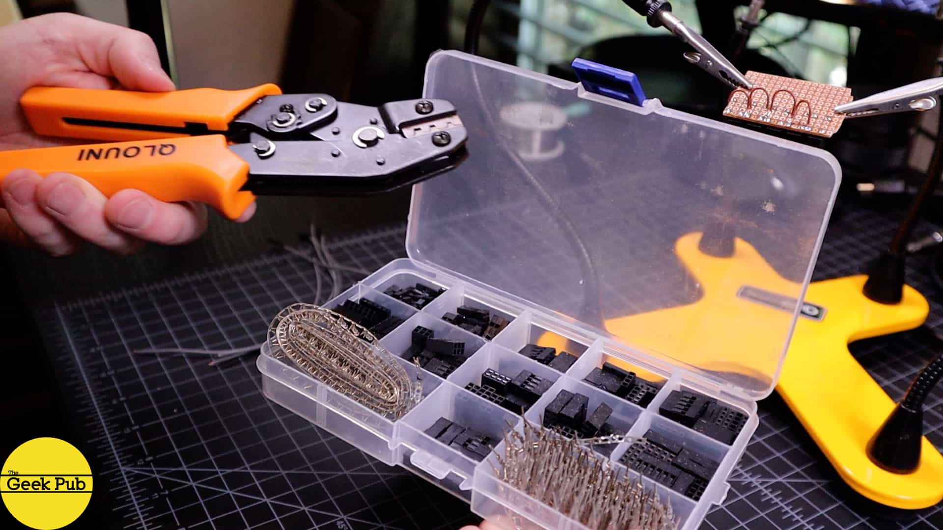
- JST connector kit w/crimper
- QuadHands helping hands
- Weller solder station
- .6mm Fine solder for circuit boards
If you plan to 3D print your case, you can get the files on Thingiverse. If you don’t have a good 3D printer, here’s the one we use and have had great luck with.
Pi1541 Build Video
Prototyping the Pi1541
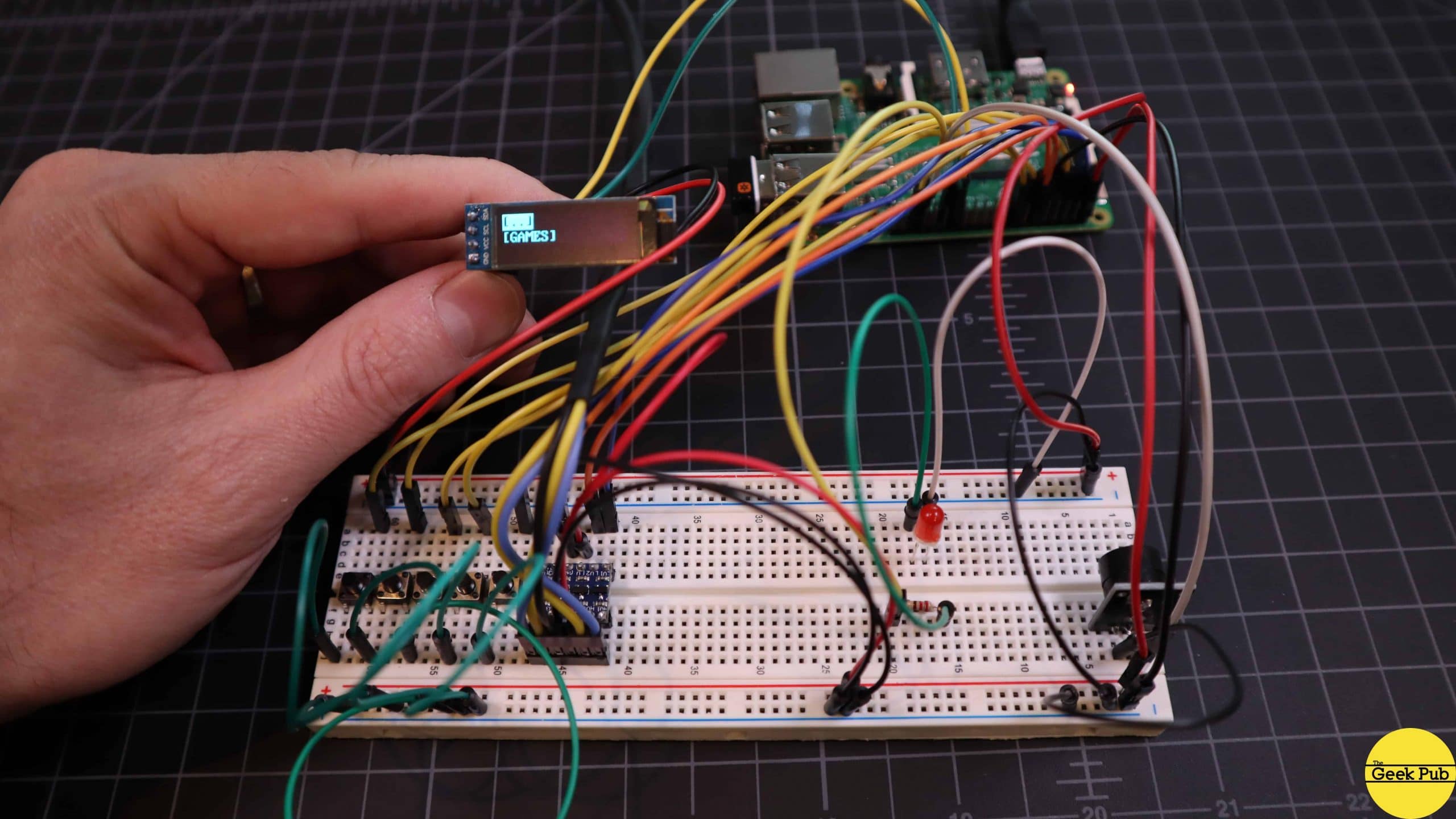
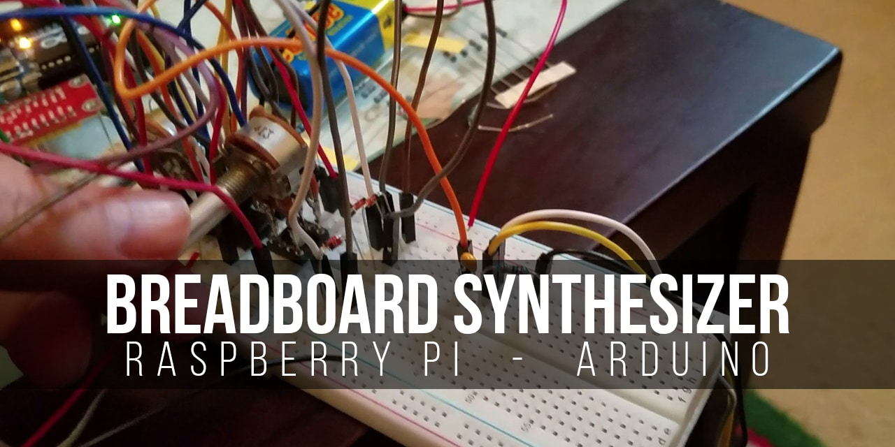
The first thing I did before building my Pi1541 is to simply prototype it on a breadboard to make sure everything actually works. This is a simple way to find mistakes and test ideas before putting the Pi1541 on a soldered board which is much more difficult to change after the fact.
It’s also important to note that as of this writing, only the
Pi1541 Wiring Diagrams
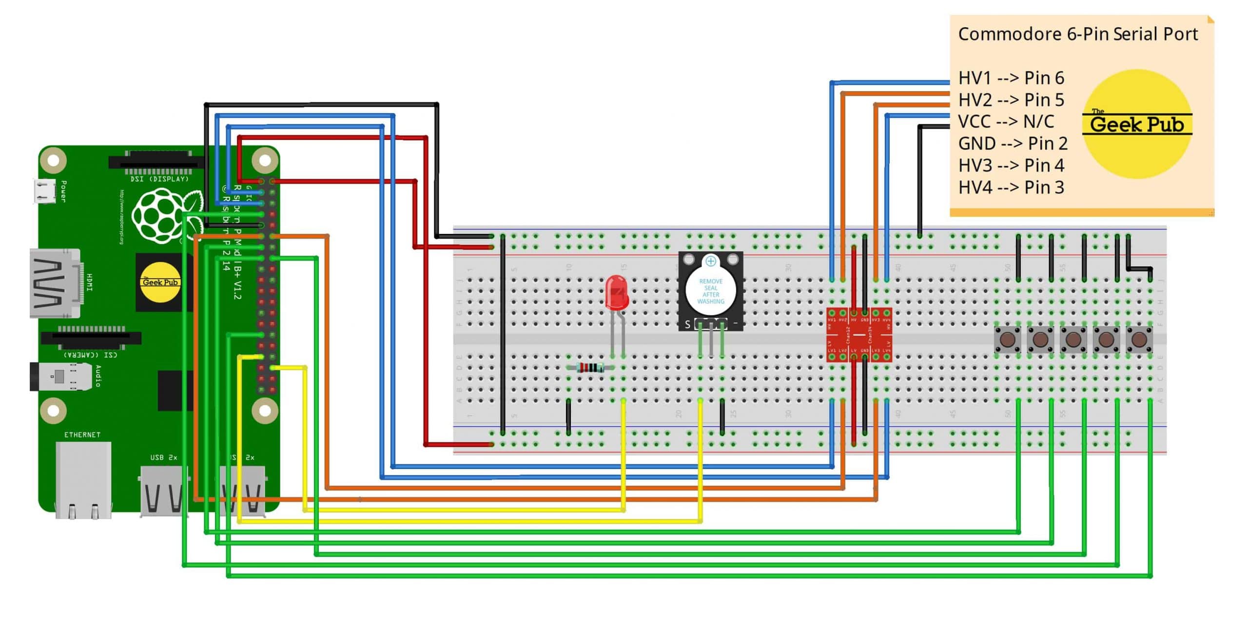
The Pi1541 comes with a wiring schematic that is decent enough to follow. However, I know so many people prefer simpler Fritzing style diagrams for these types of projects. So in order to make this project as simple as possible for you to replicate, I’ve provided both.
Pi1541 Wiring Diagram (Fritzing style)
If you’d like to just create the Pi1541 on a breadboard (or you just find Fritzing style diagrams easier), you can use this simple diagram to get you started on your project.
Pi1541 Schematic Diagram
This is the official Pi1541 wiring schematic for this project. Note that the official schematic does not show connection of the OLED display. If you decide to use an OLED or LCD display, connect the OLED displays’s pins as follows:
- OLED SDA to
Raspberry Pi PIN 27 - OLED SCL to
Raspberry Pi PIN 28 - OLED VCC+ to 3.3V rail
- OLED GND to Ground
You will need to make a change in the options file to enable this, covered later in this tutorial.

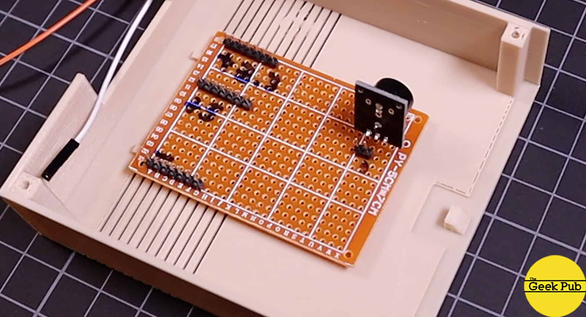
Building the OLED and Switch Board
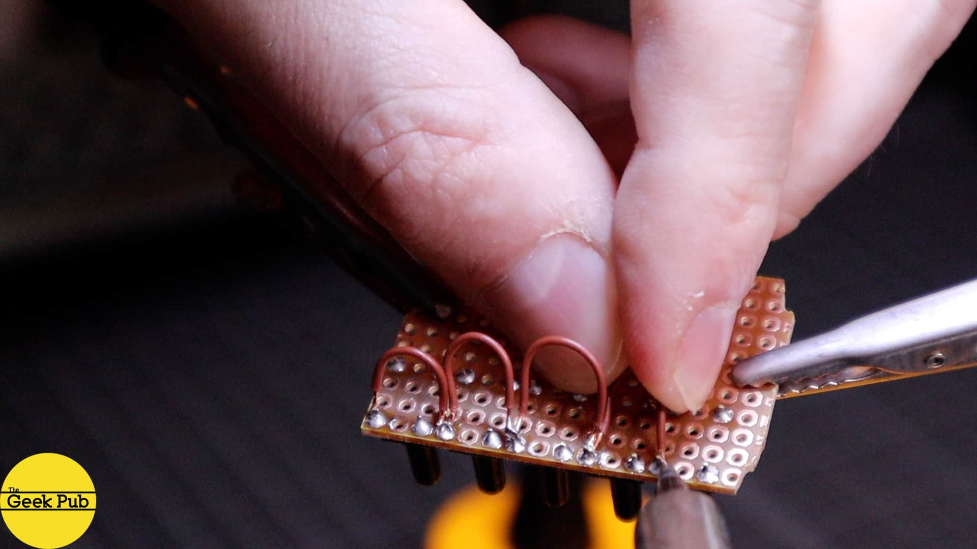
The first part I tacked was building the circuit board that will hold the Pi1541’s OLED display and its hardware control buttons. I used the circuit boards listed above and scored them with a razor knife, snapped them, and then finished off the rough edges with a little sandpaper.
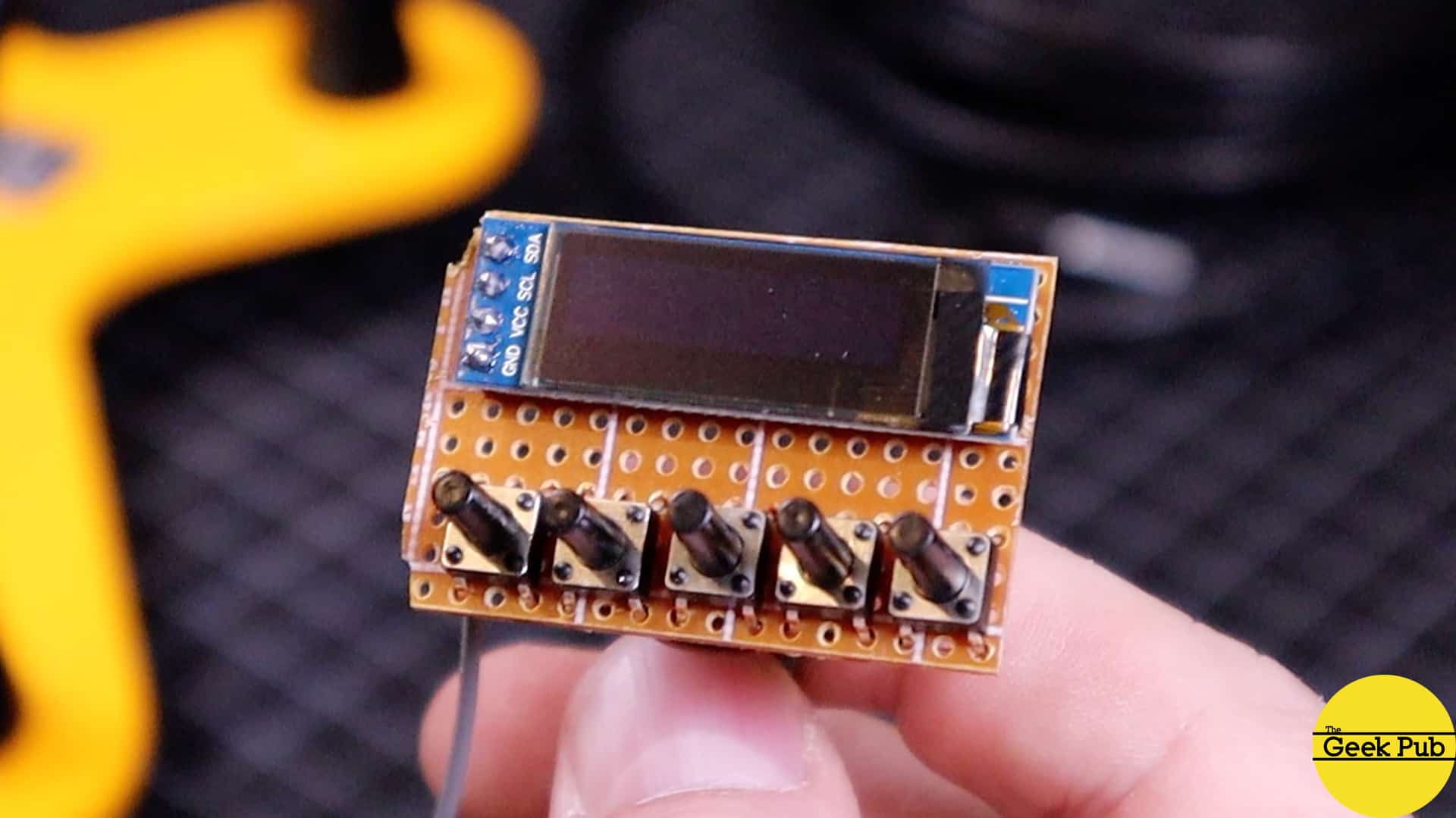
On the back of the OLED circuit board, I simply jumped all of the grounds together to make it simpler to wire. It might not be the most elegant solution, but It works just fine. The final wire is tied to a common ground.
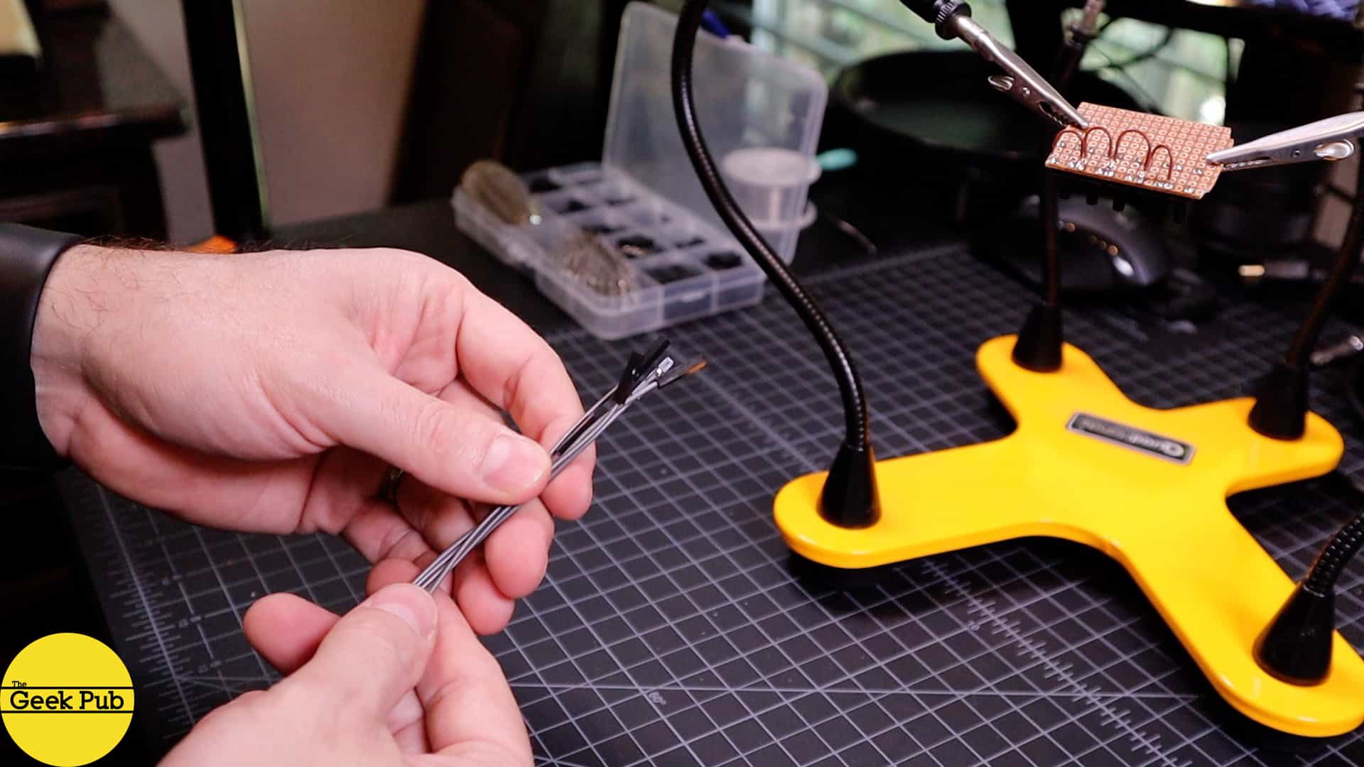
To make wiring everything to the
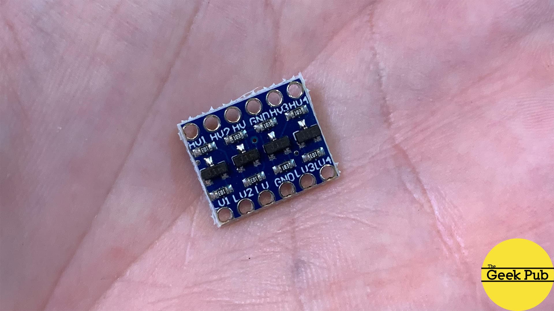
The Commodore 64 and most other Commodore machines use 5 volt serial lines. This was very common in the 1980s. Today, most everything uses 3.3 volts. The
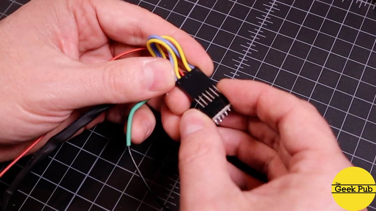
Since many of the wires in the schematic above go to common terminals such as 3.3 volt, 5 volt, and ground, I decided to make an additional circuit board to provide common headers. I also used this board to hold the passive Piezo speaker that the Pi1541 uses to make drive track movement noises. I simply hot glued this to back of the case. So let’s talk about the case next!
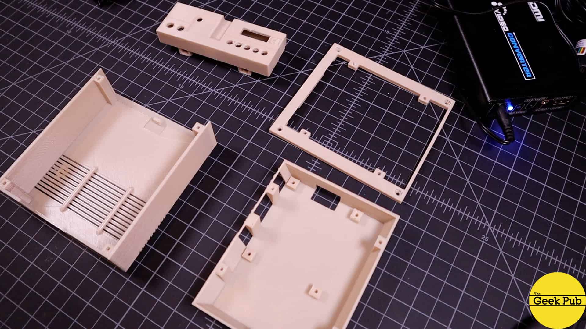
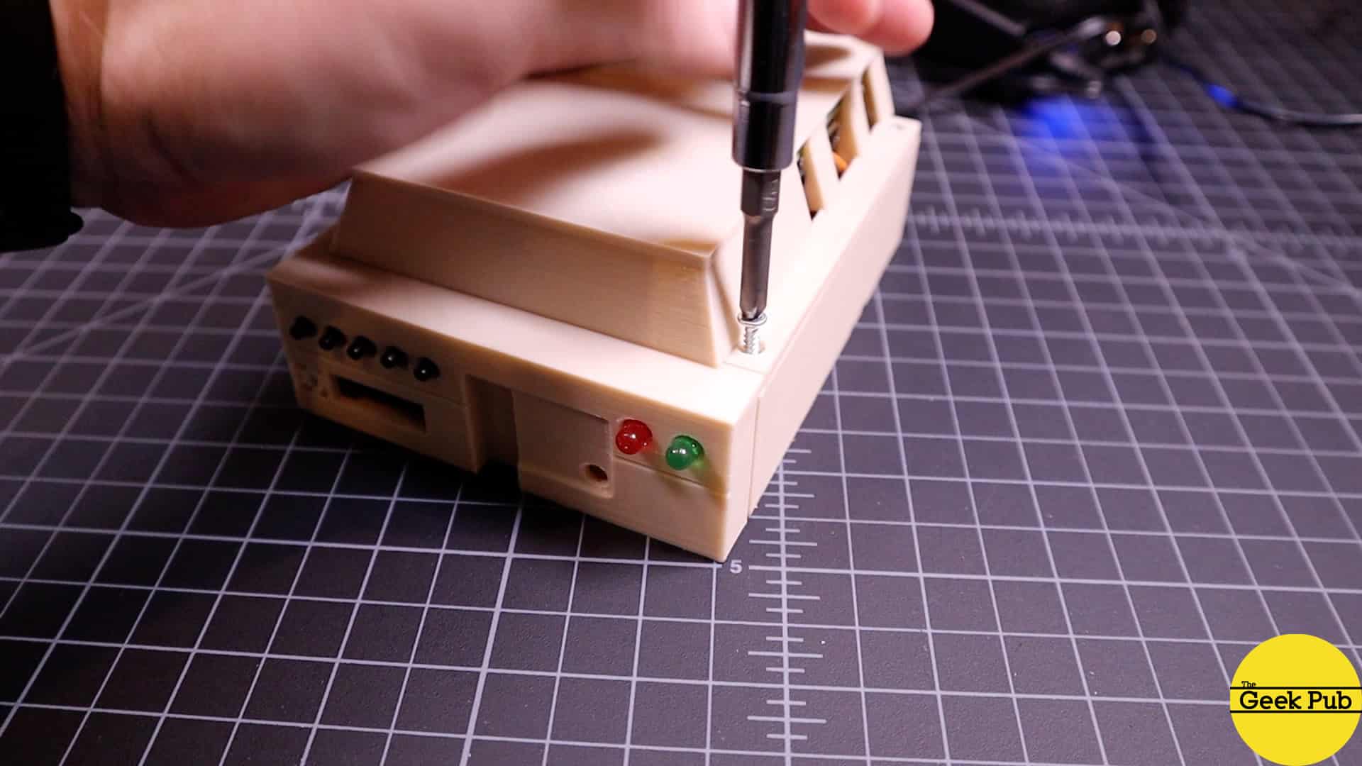
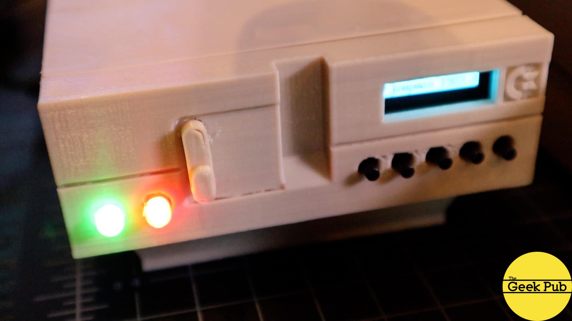
3D Printing the Pi1541 Case
Next up we need a case to put this Pi1541 into and make it look the part. To do that, I used files from Thingiverse. Eventually, I am going to remix this case and change some things to suit my liking. For one, I am going to eliminate the large hole in the back of the case and replace it with a hole designed for a wire and grommet to pass through. It works fine for now.
The thing I most like about this Pi1541 case is that is looks like the 1541-II that Commodore released a few years after production of the new C64C. It looks great!
Installing the Pi1541 Firmware
Installing the Pi1541 firmware is a completely different process than setting up the
Software You Will Need
You will need to download the following software:
- The latest version of the Pi1541 software
- The latest
Raspberry Pi Firmware (note this is not the same as Raspbian) - Latest version of the Vice emulator (to get the 1541 ROM files)
Pi1541 File System Must be FAT32
The first you need to do is obtain an 4GB or 8GB micro SD card. You can use a larger micro SD card, but you will need to partition it to only 8GB or less. This is because the Pi1541 needs to be a FAT32 file system. It will not boot from exFAT.
Using the SD card formatter, create a FAT32 file system on your micro SD card. The most common reason that setup fails when building a Pi1541 is because the file system is formatted as something other than FAT32 (exFAT, NTFS, etc.).
Building the Pi1541 Micro SD Card
Now that we everything ready, build the Pi1541 micro SD card as follows:
- Unzip the
Raspberry Pi firmware file into a temporary location on your hard drive. - From the firmware\master folder copy the following three files into the root of your micro SD card: bootcode.bin, fixup.dat, and start.elf
- Unzip the Pi1541.zip file into the root of your micro SD card. This should create a folder called 1541.
- Unzip Vice to a temporary folder on your hard drive.
- From the vice-3.x\DRIVES\dos1541 folder in Vice, copy the file dos1541 to the root of your micro SD card and then rename it to d1541.rom (note that you could also substitute jiffy.bin if you are using jiffyDOS).
- From the vice-3.x\C64 folder, copy the file chargen to the root of your micro SD card. This is the Commodore font.
- Place any .d64 images you’d like to use inside the 1541 folder. You can also create folders to organize your files (ie games, utilis, etc.).
With the micro SD card ready to go, place it into your
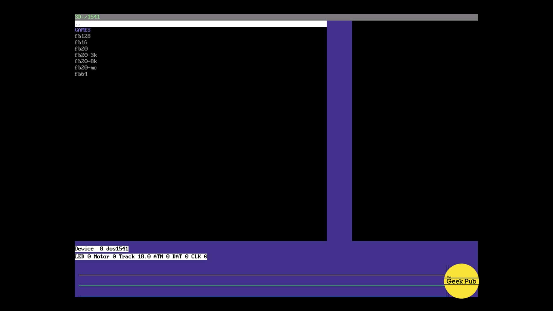
You should almost instantly be greeted with the Pi1541 home screen on your monitor.
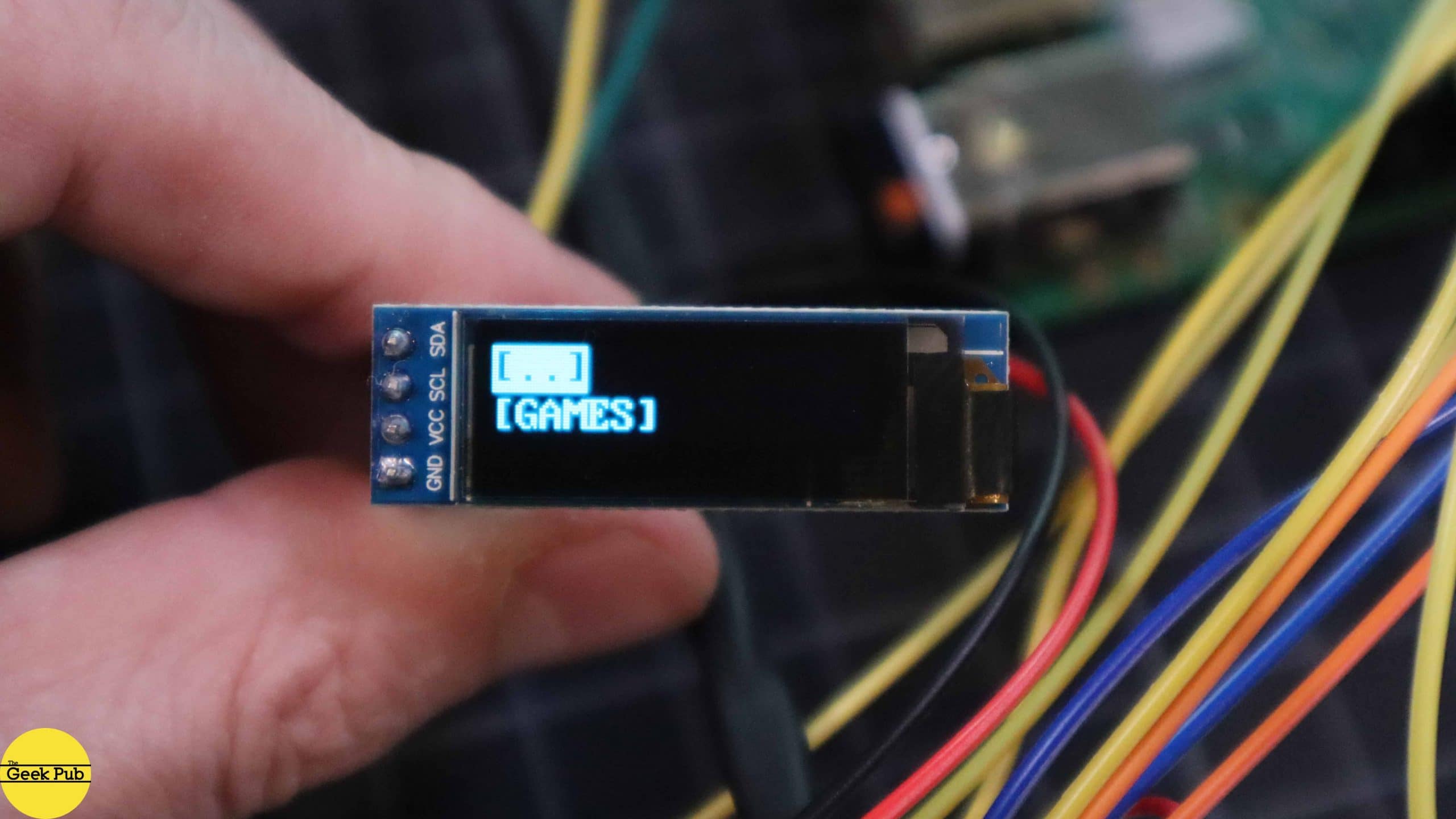
Enabling OLED Screen Support
It’s practical to have the Pi1541 connected to an HDMI monitor all the time, even though there are some fantastic bits of information it shows on the screen. The better option is to attach an OLED or LCD screen to your project. If you decide to do so, you’ll need to make a change to the options.txt file in the root of your micro SD card to enable the screen.
uncomment the following line by removing the two forward slashes from it:
[code language=”bash”]
//LCDName = ssd1306_128x32
[/code]
This works with OLED screen we’re using in this project. If you’re using a different screen, uncomment the line that matches your screen.
Additionally, if you’re following our wiring diagram above, you’ll need to uncomment the following line to configure Pi1541 to use our alternate I2C pins (27/28 rather than 3/4).
[code language=”bash”]
//i2cBusMaster = 0 //SDA – pin 27 SCL – pin 28
[/code]
Lastly, you’ll probably want to uncomment the following line in order to enable the CBM native font (which just looks amazing!).
[code language=”bash”]
//ChargenFont = chargen
[/code]
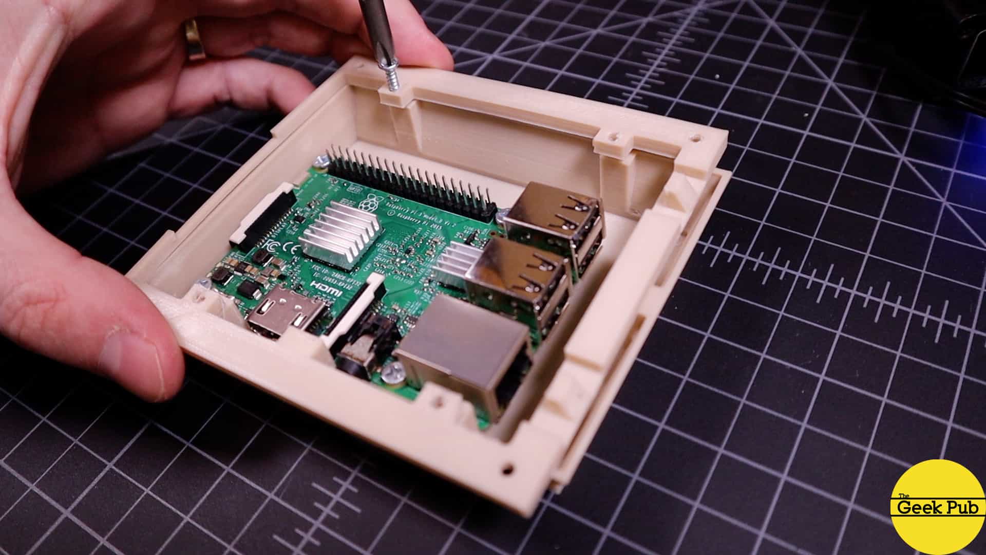
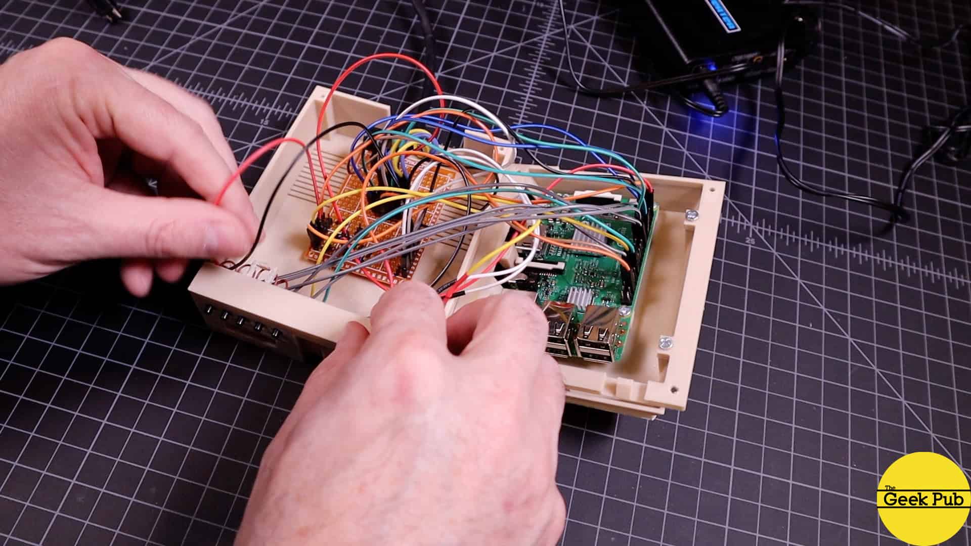
Final Assembly of the Pi1541
Once you’ve got the firmware loaded and you’ve tested everything, its time to begin final assembly. If you’re using the same 3D printed Pi1541 case that we chose, you’ll just need 6 small screws from Amazon or Home Depot.
About the only hard part of final assembly is carefully tucking all of the wires into the Pi1541 case without damaging anything. If you used the JST connectors like I did, it helps to feather all of the wires into place after making your final connections.
Using the Pi1541
Using the Pi1541 couldn’t be much simpler. There are five buttons across the front of the device. These buttons are for operating the drive emulator.
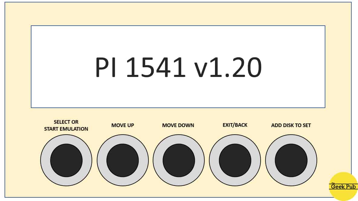
- SELECT / START EMULATION – This button selects a folder (and opens it), or selects a disk image to start emulating.
- MOVE UP – Moves the cursor selection up one row.
- MOVE DOWN – Moves the cursor selection down one row.
- EXIT / BACK – Exits the current folder (back up one level).
- ADD DISK TO SET – For adding disk images to a multi-image set. Handy for games that use multiple disks.
If you’ve correctly placed all of your disk images (some people call them ROMs) into the 1541 folder, you should be able to push the select button on the 1541 folder and see all of your games. use the up/down buttons to scroll through the list and finally hit the select button to mount the image and start emulation.
If you used folders, use the back/exit button to go up one level.
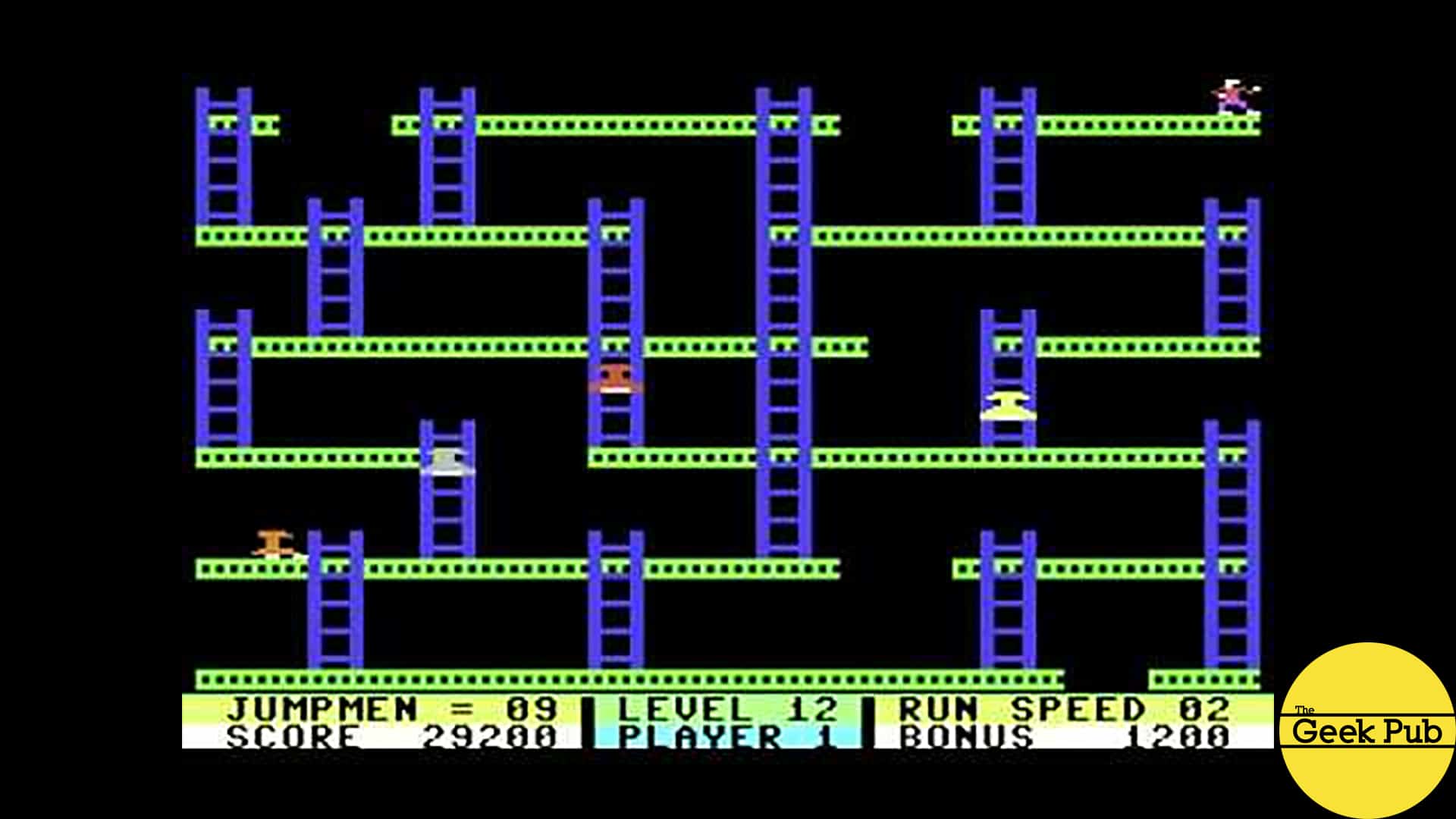
Trying out the Pi1541
Now we’re ready to use the Pi1541 to do what we all love best, play some amazing 1980s retro 8-bit games in all of their glory! I started out by playing Jumpman. It turns out I really don’t remember how to play this game and totally sucked at it!
Next up I tried Spelunker, I am so much better at that game. Spelunker was one of my all time favorite games on the C64. I played it for hours on end as a teenager.
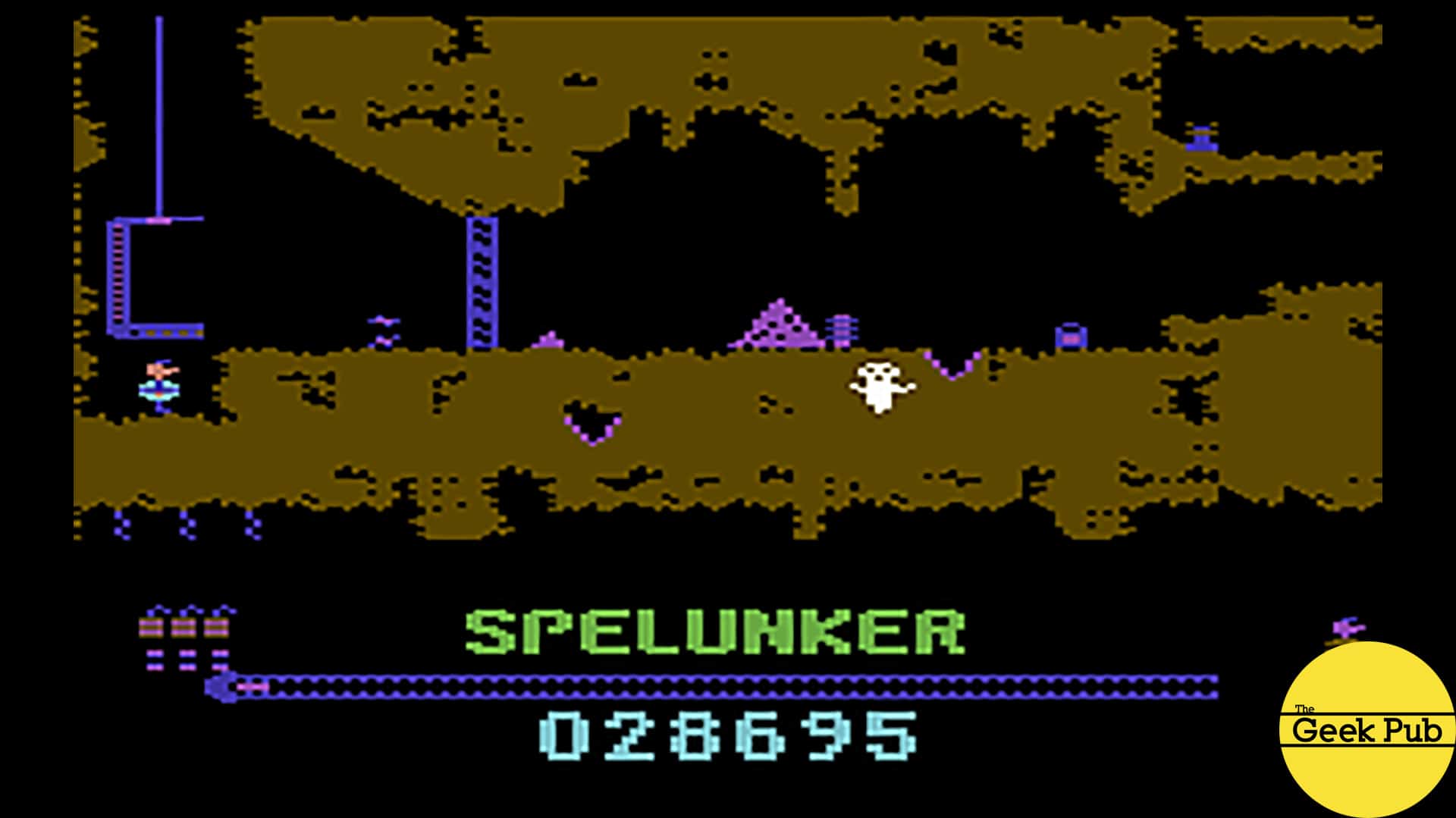
The Pi1541 is 100% emulation of a real 1541. It even supports all of the LEDs and drive noises you’d expect to hear out of a real 1541 disk drive!
Some Things I Would Do Different
If I were to rebuild this Pi1541 there are just a few minor things I would change or do different:
- I would reprint the case in high resolution mode. I used draft mode to save time and there are pretty ugly spots. Draft mode took hours off the print job though.
- I would remove the large hole in the back of the case and replace it with a hole for the wire and a grommet.
- I would make a single 40 pin header with the JST connectors making it a single connector to the
Raspberry Pi . This would make the Pi easy to remove and replace without rewiring every time.
Well I hop you enjoyed this article and our fun Raspberry Pi1541 build tutorial! If you run into any problems or have any questions, leave a comment below and we’ll do our best to help you out!
[adinserter block=”5″]


5
This “1541” just became my new favorite thing! You should consider selling these on your site!
Unfortunately, I don’t own the rights to the BIOS so I am unable to offer them.
Such a great tutorial Mike! I will be building this!
Mike, is it possible to use a Raspberry pi 2 instead of the model 3?
Thanks,
Danny
As far as the docs go, they say only Pi3 or Pi3B+.
Well, I do have a pi 3B+ that I am not using, I guess it will be used for this project. LOL
Hi, Mike! Thanks for helping me breath new life into my C64 and giving me a fun weekend project 🙂
Regarding JiffyDOS, I can’t seem to get it to load. Even after scrubbing all other ROMs from the SD card. I don’t get any errors, and the pi1541 continues to function as expected, but I’m not getting an indication that JiffyDOS has been loaded.
Do I need to have the supporting hardware to make it work? I downloaded the JiffyDOS images from the official site and picked a few out of the bundled zip that were referenced in the options file already.
Thanks again!
Hi Mike, I’m a big fan. Glad you found my project useful.
Hey Steve – I sent an email before this project hoping to “interview” you but never heard back. Would still love to talk sometime!
This is my favorite project you have ever done. Hands down! I must do this now. Thanks!
4
Hi, great article. For it all went right for me at the first try. The only thing that caused a problem was that the 4GB SD card I dug up from an older smartphone is unable to boot the PI. Once I had that replaced it worked like a charm.
The only thing I did notice was that the Turbo Marco Pro editor doesn’t work. I use the same d64 file as in the VICE emulator. But everything else just works.
So, thank you very much for these very high quality articles.
This was incredibly helpful. This is probably the first (ever) project I’ve done where it worked on the first attempt. Thanks!
5
Does the pi1541 work with vic20 as well. I assume it would but just wanted to check. Thanks!
Yep
0.5
I modified this build, I printed the case and built the OLED / button header just like the article / instructions. But I bought a Pi1541 hat kit and built the kit without soldering the buttons, OLED screen and LED’s to the board. Instead I solder extension wires from those components to their respected places on the board. Now I have 2 ports on the back with the option to daisy chain it with a real 1541.
This is awesome. One question. Any reason this wouldn’t work with a PiZero?
Should work fine!
where the green led is conected?
I would like to know about the Green led too.thank you!
Very interesting project for this weekend!