Blog
Space Invaders Pinout
I recently restored a Midway Space Invaders cabinet that had numerous issues with the motherboard set. It was acting very flaky. I thought I would share some of the information starting with the Space Invaders Pinout. The board I dealt with was a Space Invaders Deluxe board.
The Space Invaders pinout can vary between brands of boards (Midway, Taito) and version (Standard, Deluxe). However, most follow the same pinout.
Space Invaders Card-Edge Pinout
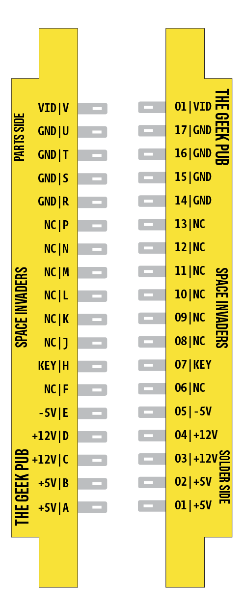
Let’s start with the most important Space Invaders pinout: the 36-pin card-edge connector. This connector is responsible for two main things. Supplying power to the board set, and video output to the CRT.
The card-edge connector is on the motherboard/main board. This is the board that houses the CPU, memory (DRAM), and ROM chips.
One important thing to note about this connector is that the pins on the front and back of the card-edge are bridged. That means the card edge needs to proved +5v on both pin A and 01. If you use a replacement space invaders card-edge connector you’ll need to make sure bridge the the pins on the connector with your wire. The Space Invaders pinout is a bridge connector! Many people fail to realize this and their board set will not function as a result.
Space Invaders Daughterboard Pinout
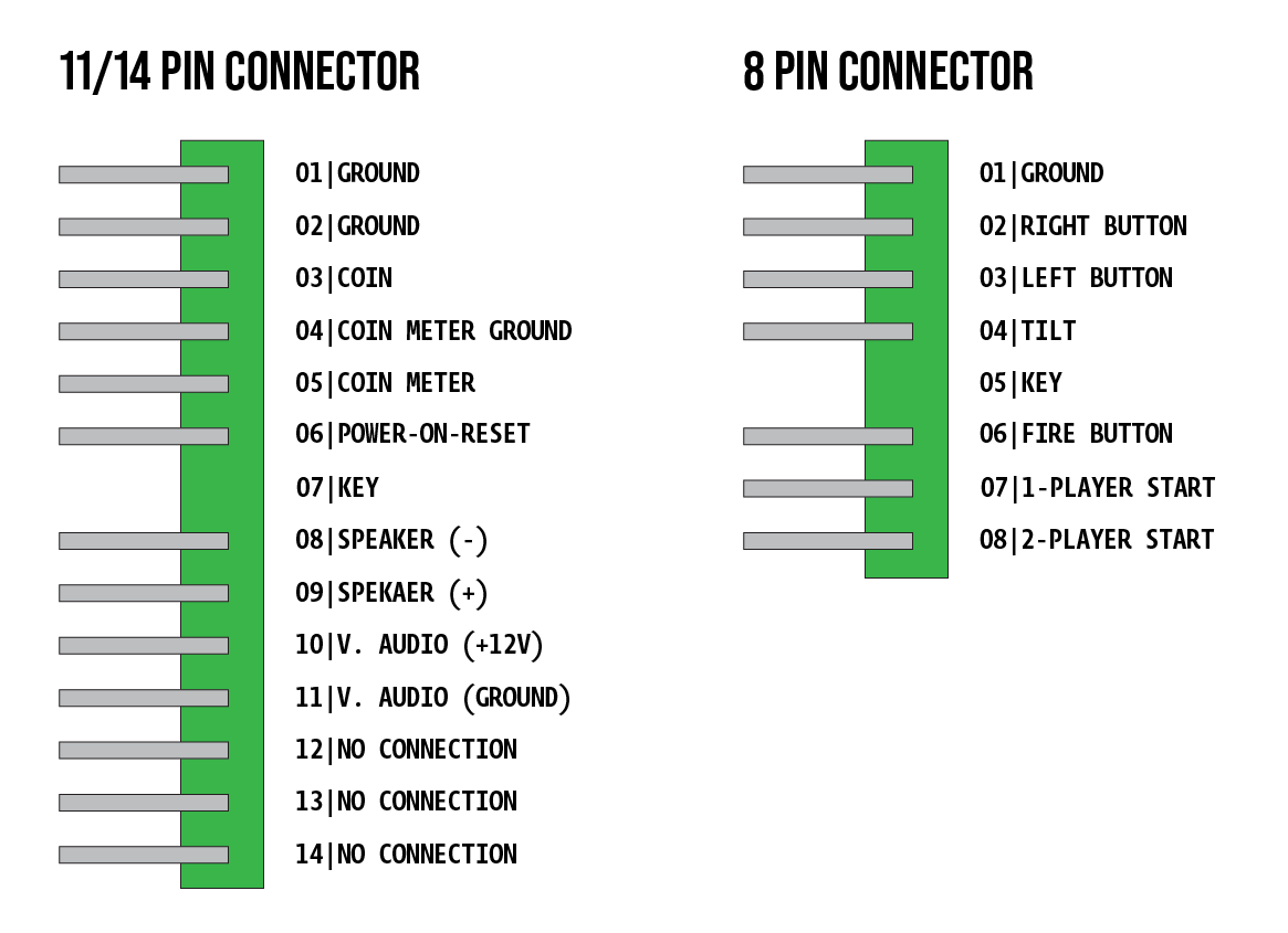
On the Midway Space Invaders L-Board there are two boards. The mainboard (or CPU board) above, and the daughterboard. The daughterboard (some call this the soundboard) has two additional connectors on.
- 11/14 pin: Connects to coin mech, power-on-reset, and speakers.
- 8/ pin: Connects to the buttons
It should be noted that this pinout confuses a lot of people because the connector is split. For example if your board has a 14 pin connection, it may have two separate connectors with a space between them. For example a 6 pin, and a 7 pin connector. This is actually a 14 pin connector. The space is supposed to be the key to insure you insert it in the correct orientation.
Space Invaders Pinout Additional Notes
Adding a few notes here to help you along with your Space Invaders endeavors!
- Space Invaders can be VERY picky about voltages. If you’re power supply is only putting out 4.8 volts you may have issues with your Space Invaders acting funny. Check your power supply with a meter and make sure you have the correct, +5, -5, and +12 volts coming from your power supply unit.
- If you are bench testing your Space Invaders and you don’t have the daughterboard wiring harness connected, you will run into issues of a garbage screen. To correct this, make sure pin 6 on the 11/14 pin connector is tied to ground.
- If your game is misbehaving, and you’re sure you’ve followed the Space Invaders pinout correctly, then we highly recommend you download and burn the Space Invaders Test ROM. This ROM goes in ROM position H and will help identify what is wrong with your board (bad RAM, etc).
- Be careful about using pinouts diagrams without observing them on the board. Many of the websites out there are flat out wrong and following them could cause damage. Also, its possible you may have them upside down! Look at your board. Note the KEY position. Make sure you have the orientation correct. On Space Invaders, if you reverse the card edge you’ll be shorting your power directly to ground!
On the pinouts for the 11/14 pin connector, pins 10 and 11 are swapped in your diagram.
10) Audio GND
11) Audio +12V
12) Flip screen to the monitor for the table
13) GND