Blog
Oscilloscope Tutorial (Learn the Basics)
Oscilloscopes are super handy tools to have around the workshop. With an oscilloscope you can test electronics and devices to see if they are functioning correctly, and make repairs. In this article and video, we’re going to do a basics 101 oscilloscope tutorial and learn how they work!
Watch The Oscilloscope Tutorial Video
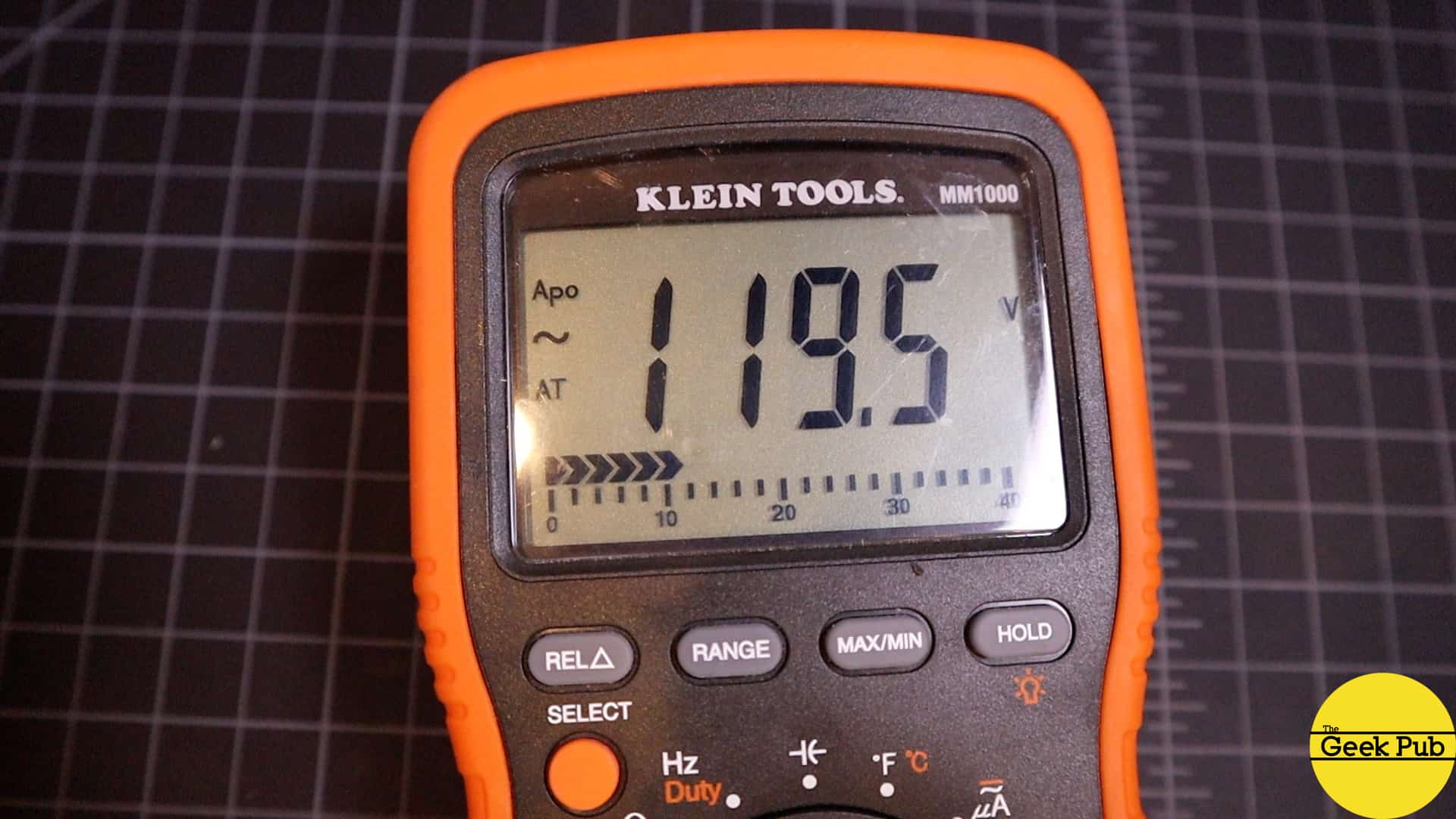
Let’s start this tutorial with a little comparison. You’re probably already familiar with a multimeter, but let’s quickly review because I think it will help you understand the oscilloscope a little better. When measuring voltage, a multimeter takes a single “point in time” reading of a circuit. For example, when connected to a 9V battery it will read 9V DC on the screen, just as you’d expect.If we hook the multimeter to our mains power outlet it will show somewhere around 120V AC on the screen depending on where you live (or around 220V AC if you live in certain other countries). Again, these are point in time readings. And the truth is, if you measure AC voltage over time it’s not outputting 120V at all! This is where the oscilloscope comes in!
RELATED: Multimeter Basics 101
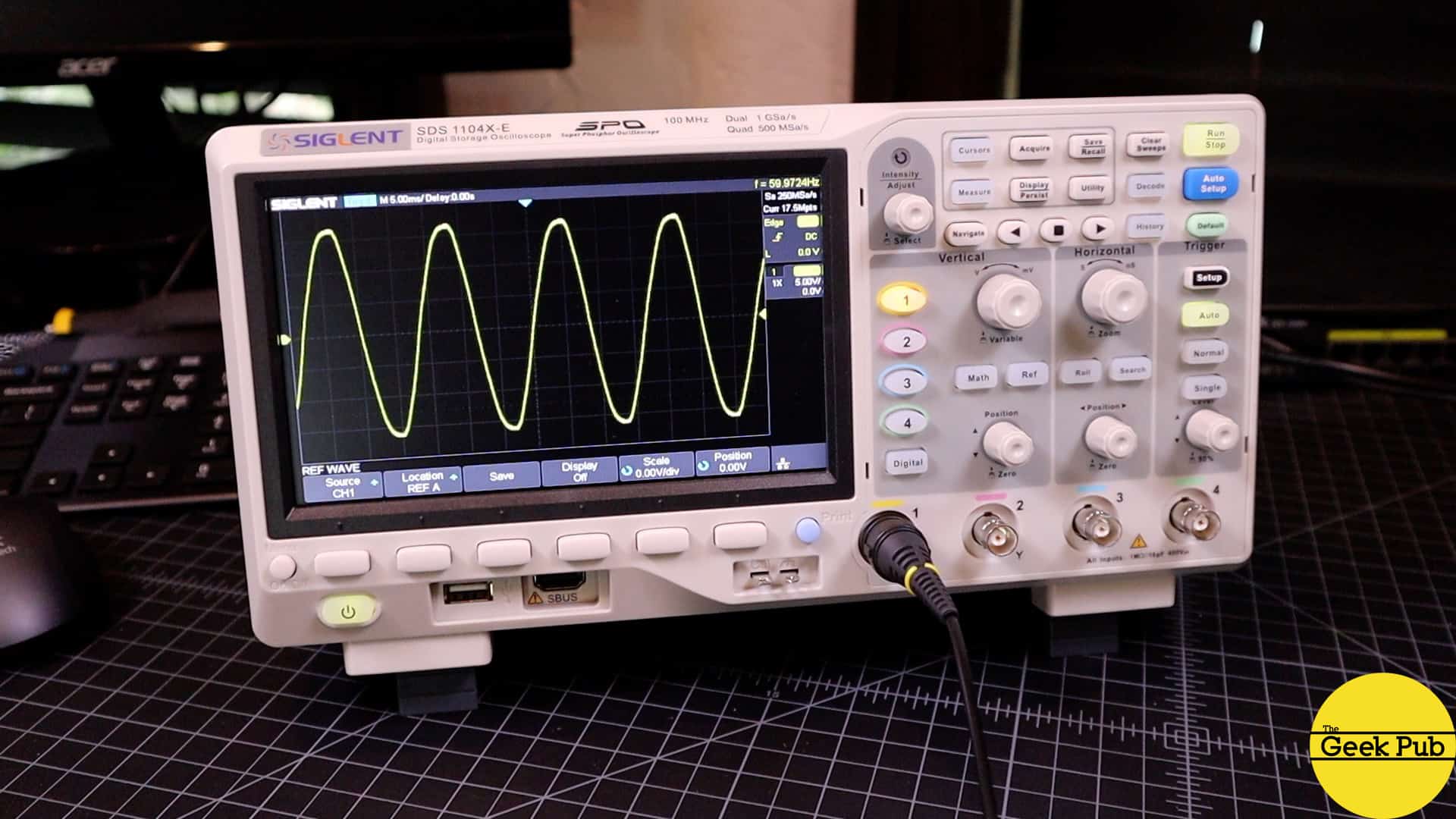
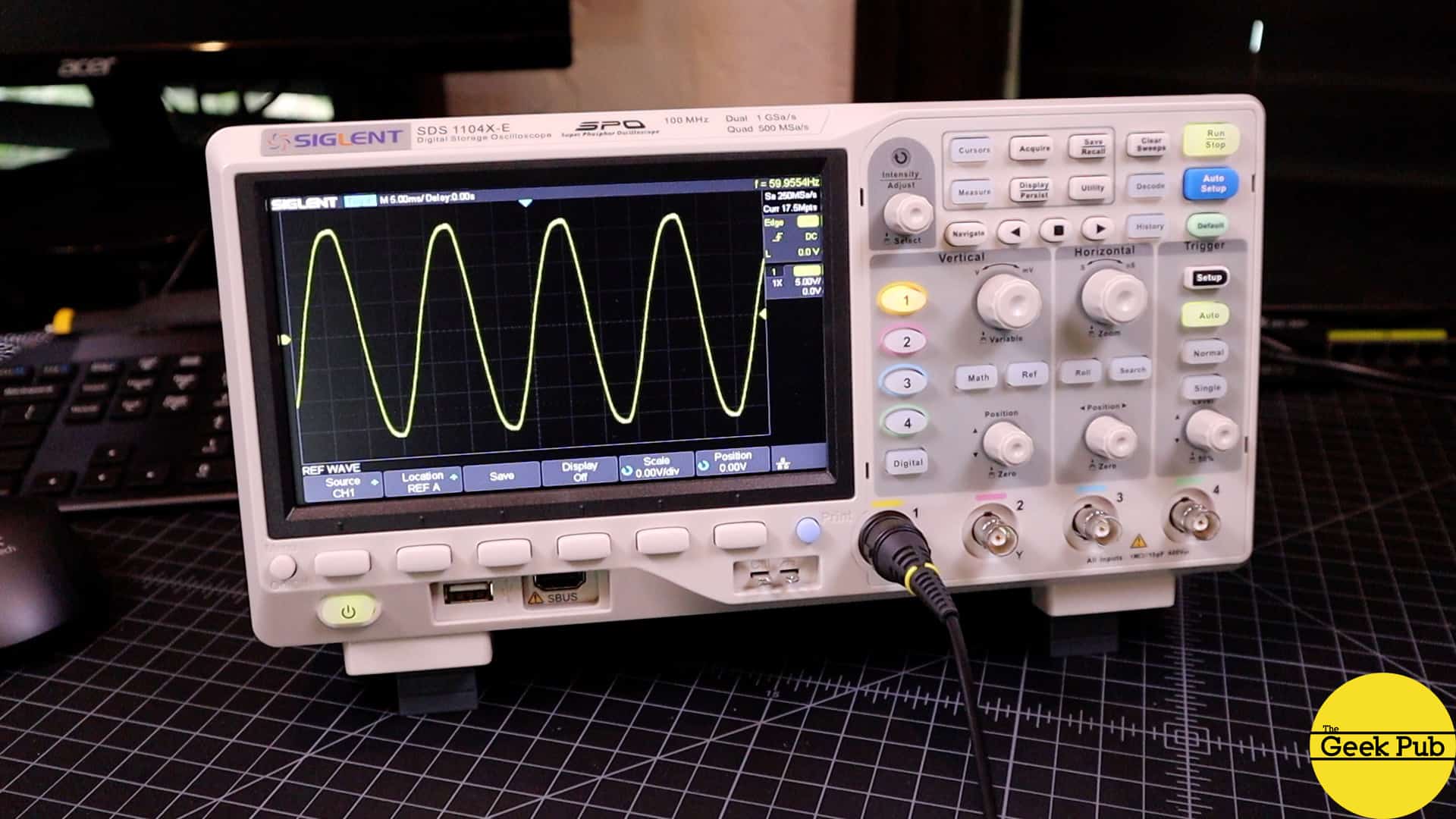
The Oscilloscope I am using is the Siglent SDS1104X-E. It’s a 4 channel scope and its a great buy for the money. I’ve also got a complete write up on my picks for the top 3 oscilloscopes for first time buyers.
Oscilloscope Tutorial and Basics
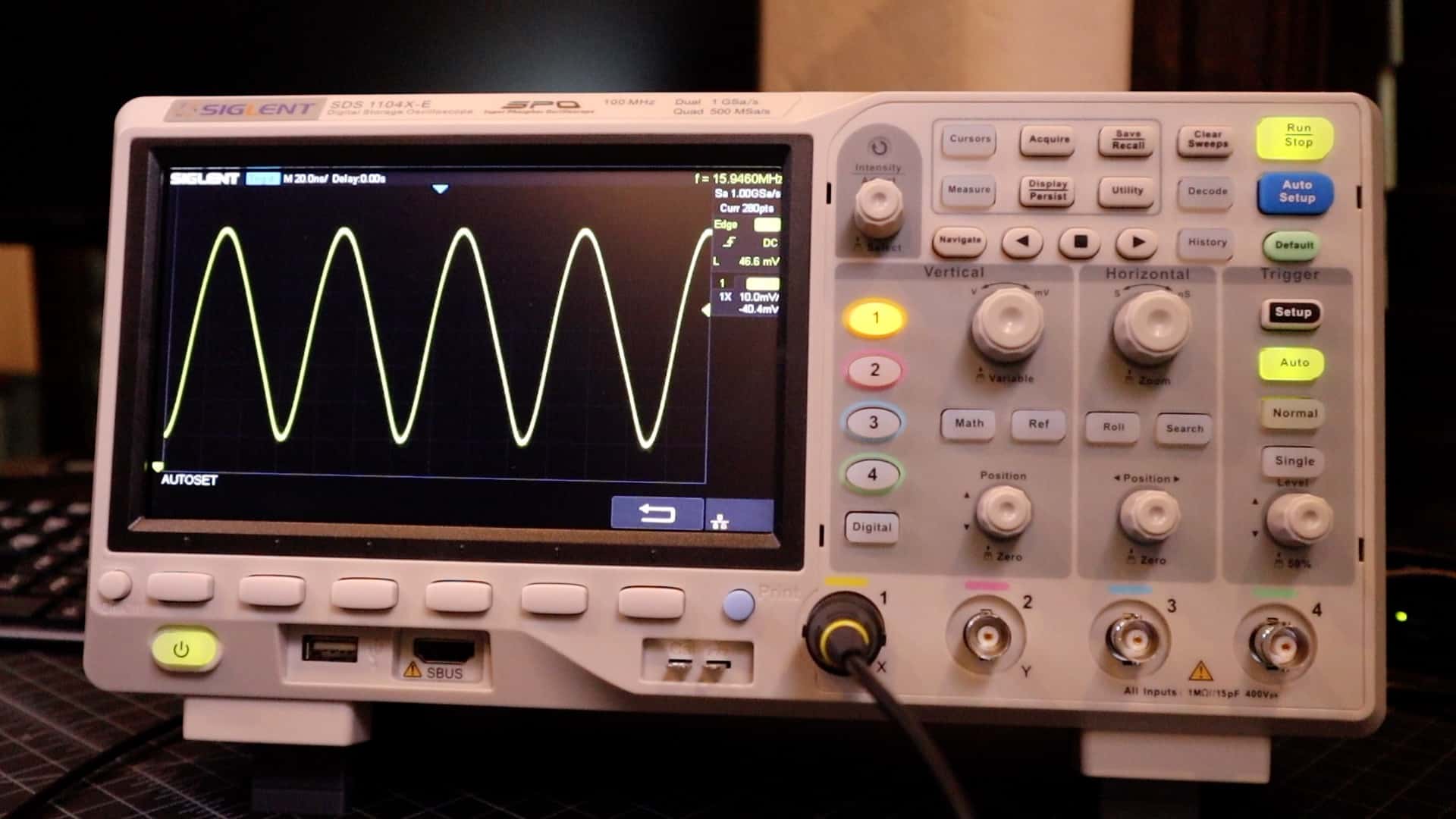
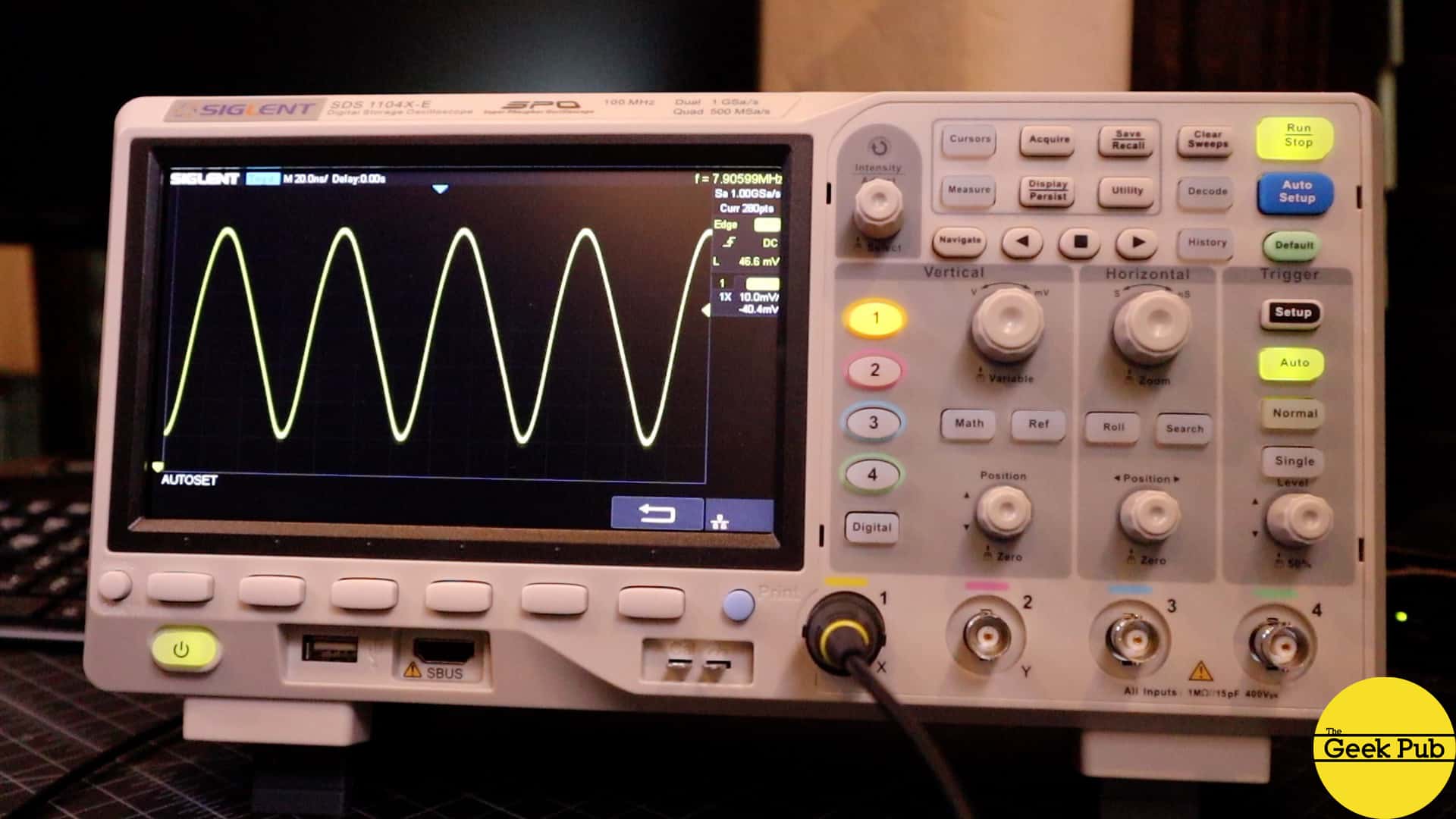
Oscilloscopes allow you to measure a circuit’s voltage over time, taking many thousands of readings and plotting them on the screen over that time. Many modern oscilloscopes can even write this output to a file for later in-depth review on a PC or Mac. You can see when I connect the oscilloscope to the 120V AC mains in my house, that the voltage isn’t 120V after all. It is constantly changing in this waveform pattern. It’s constantly changing from -170V to +170V! This is why it is called alternating current!
RELATED: Understanding Voltage Tutorial
A multimeter will just show the average reading of this output in real-time, or more accurately the Root Mean Square (or RMS) reading. It takes an oscilloscope to see what’s actually happening!
Understanding the Oscilloscope Display
Now let’s take a look at the oscilloscope’s display so that we can understand exactly what is being represented. The display is made up of a grid. The size of this grid varies by oscilloscope brand and model, but they all work basically the same. The horizontal axis of this grid represents the time scale, while the vertical axis of the grid represents the voltage reading.
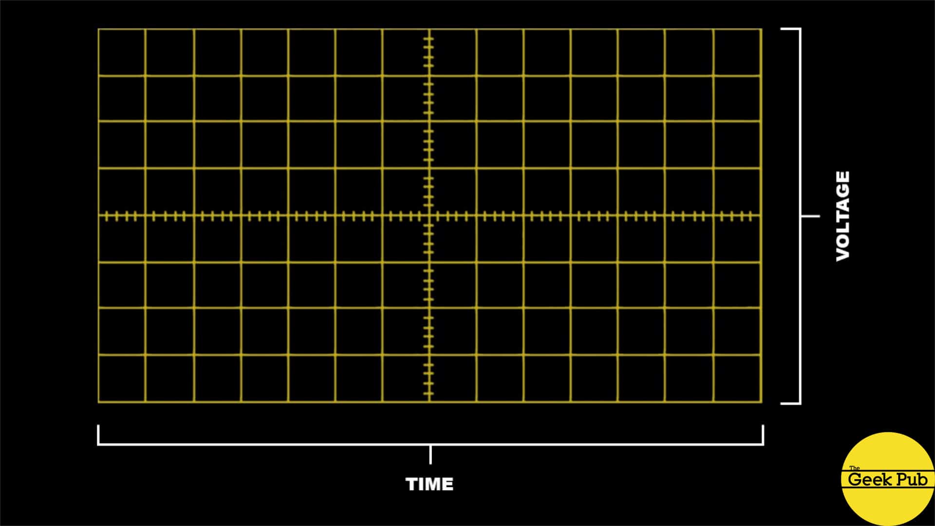
Each box in this grid is called a “division”. These divisions are configurable with the knobs on the front of the oscilloscope, so that they can represent larger or smaller scales.
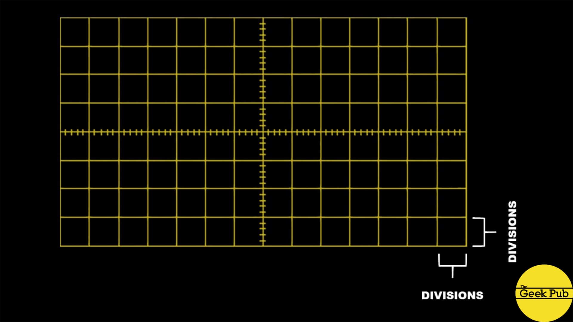
By turning the horizontal control knob for example, we can make the divisions represent a longer or shorter period of time. Or by turning the vertical knob, we can make the divisions represent a smaller or larger voltage scale. This is in effect a zoom feature of the oscilloscope allowing you to zoom in and out of the signal you are capturing. It’s also handy for when a signal is simply too large to fit on the screen, you can zoom out to see it.
RELATED: The Best Oscilloscopes for Hobbyists to Buy
Understanding Oscilloscope Waveforms
Now let’s take a little deeper look at these waveforms. If we look back at the signal from our standard 120V house mains, you can see it forms a nice wave pattern. This pattern is cycling at 60 times a second between -170 and +170 volts. This type of waveform is called a sine wave. Sine waves represent analog signals.
Let’s take an Arduino and connect one of its digital output pins to the oscilloscope. I’m going to set it light an LED, but only at 50% brightness. Here’s the code if you want to try it for yourself. Just attached the Oscilloscope’s probe to pin 6 and ground.
int OSCOPE_PIN = 6;

void setup() {
  pinMode(OSCOPE_PIN, OUTPUT);
}

void loop() {
  analogWrite(OSCOPE_PIN, 128);
}
What we see on the oscilloscope is quite different. If you’re thinking it looks like its just cycling off and on the power, but keeping the voltage at 5V, you’re exactly correct. This type of signal is called a square wave and will typically cycle by outputting zero volts for a period of time, followed by a specific voltage such as 5 volts for the same period of time.
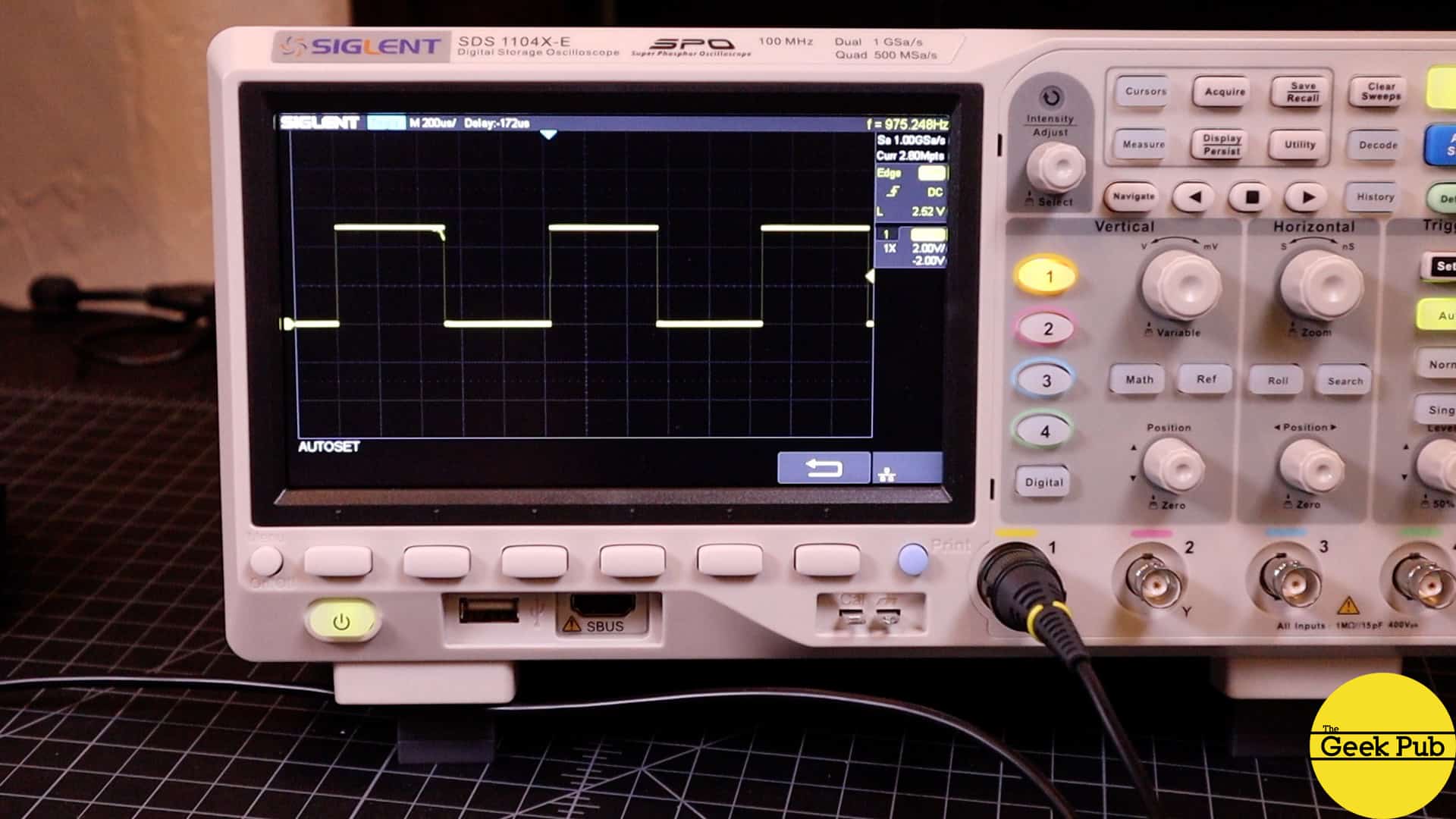
What do you think the voltage reading will be if we hook this circuit up to our multimeter? If you guessed approximately 2.5 volts you would be correct. A 5 volt square wave voltage at 50% duty cycle will produce 2.5 volts RMS! If I change the duty cycle by setting the PWM output on the Arduino to just 10% you’ll see exactly what you’d expect. Now the voltage is only 5V for 10% of the time, of zero volts for 90% of the time. This will translate to just under 1V on our multimeter.
The Oscilloscope Position Knobs
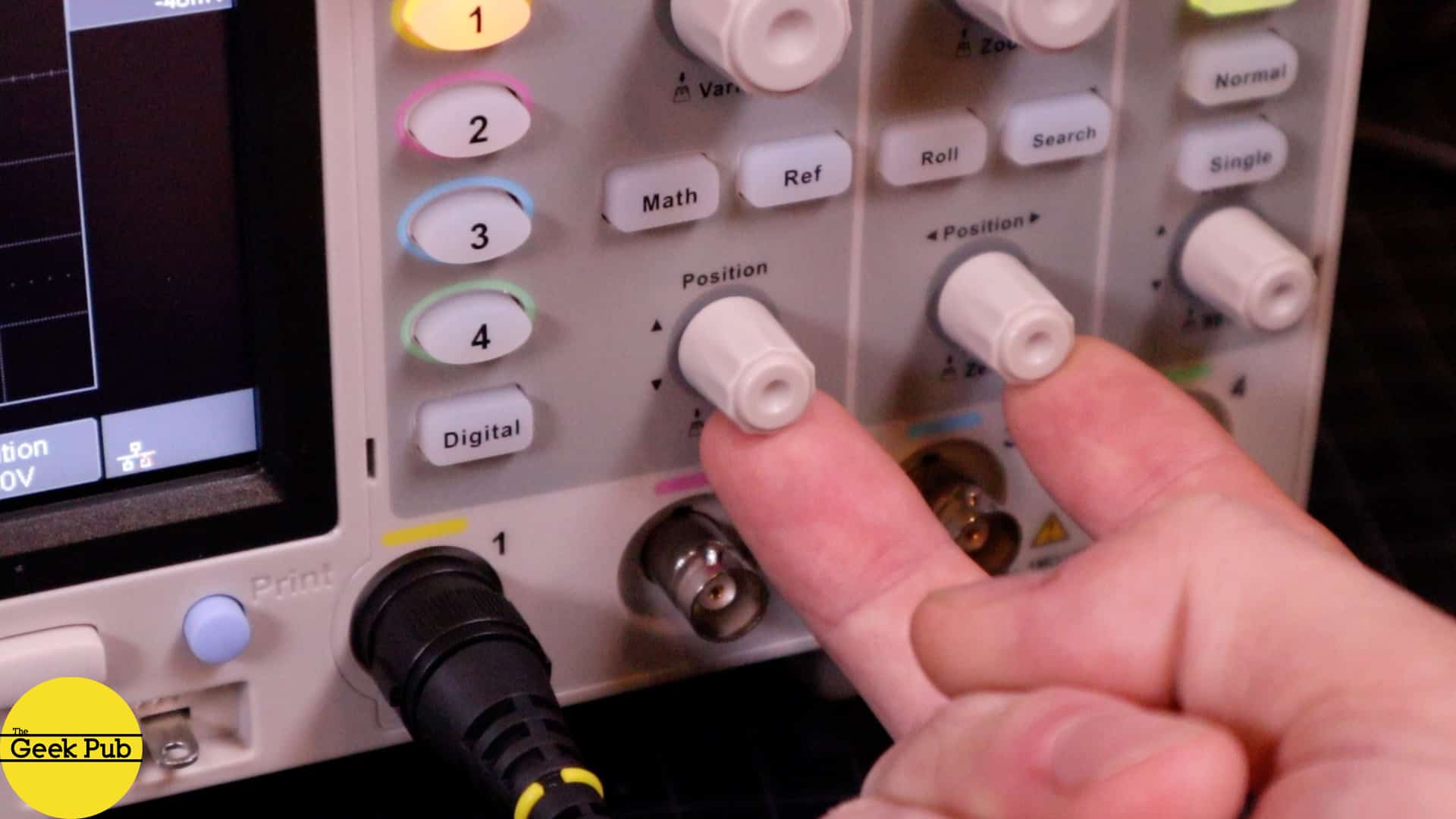
Next up in our oscilloscope tutorial, let’s talk about the positioning knobs. These are the horizontal and vertical positioning knobs. Turning the horizontal position knob lets you adjust where the waveform starts and stops on the screen and allows you to line it up with divisions should you choose. Turning the vertical position knob allows you to move the signal higher or lower on the grid making some signals easier to read. (This makes a lot more sense in the video above).
Probes and Channels
Oscilloscopes generally have between 1 and 4 channels. The probes connect to these channels using standard BNC connectors. Having more than one channel of course allows you to view more than one signal on the screen at the same time. Each channel will be represented by a different color. The probes have some pretty cool features on their own.
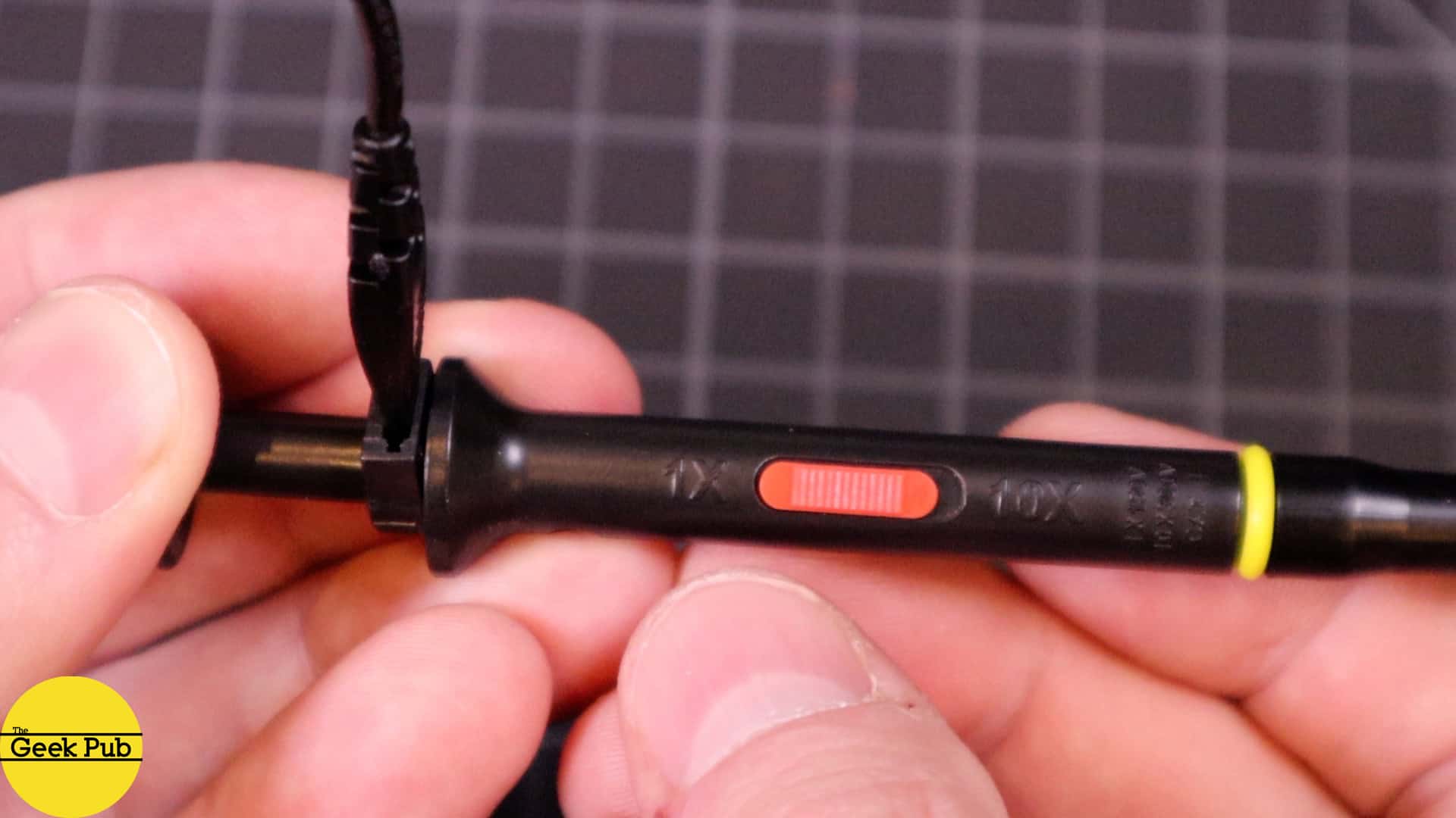
First, most probes have 1X – 10X button on the side of them. Moving the button to the 10X position attenuates the probe by a factor of 10. This is done in most brands by connecting an internal 9 Mega-Ohm resistor. You’ll most likely use your probe in the 10X mode most of the time as it is the more accurate setting for most applications.
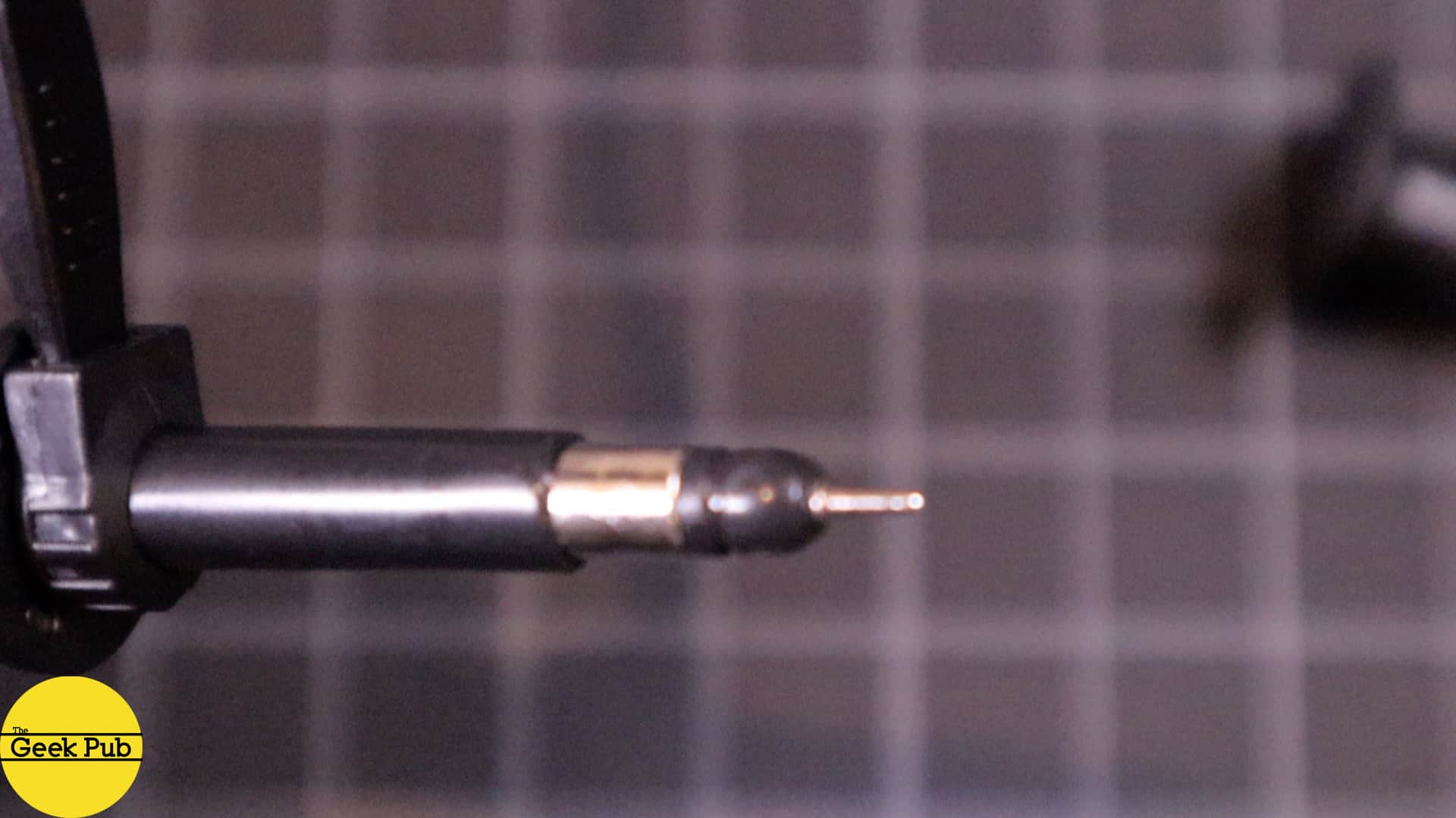
At the end of the probe you’ll see the tip and a ground lead. The ground lead or course connects to the ground on the device you are probing, or earth ground if your device has one. The tip of the probe opens by squeezing it, and offers a sprung hook to easily connect to pins or wires in your electronic devices.
However, in some cases this hook is not ideal. With most probes you can remove this hook by pulling gently to reveal a single pin probe that can reach some hard to get places. This is a super handy feature!
Using the Oscilloscope in the Real World
An oscilloscope can be very handy in everyday life!
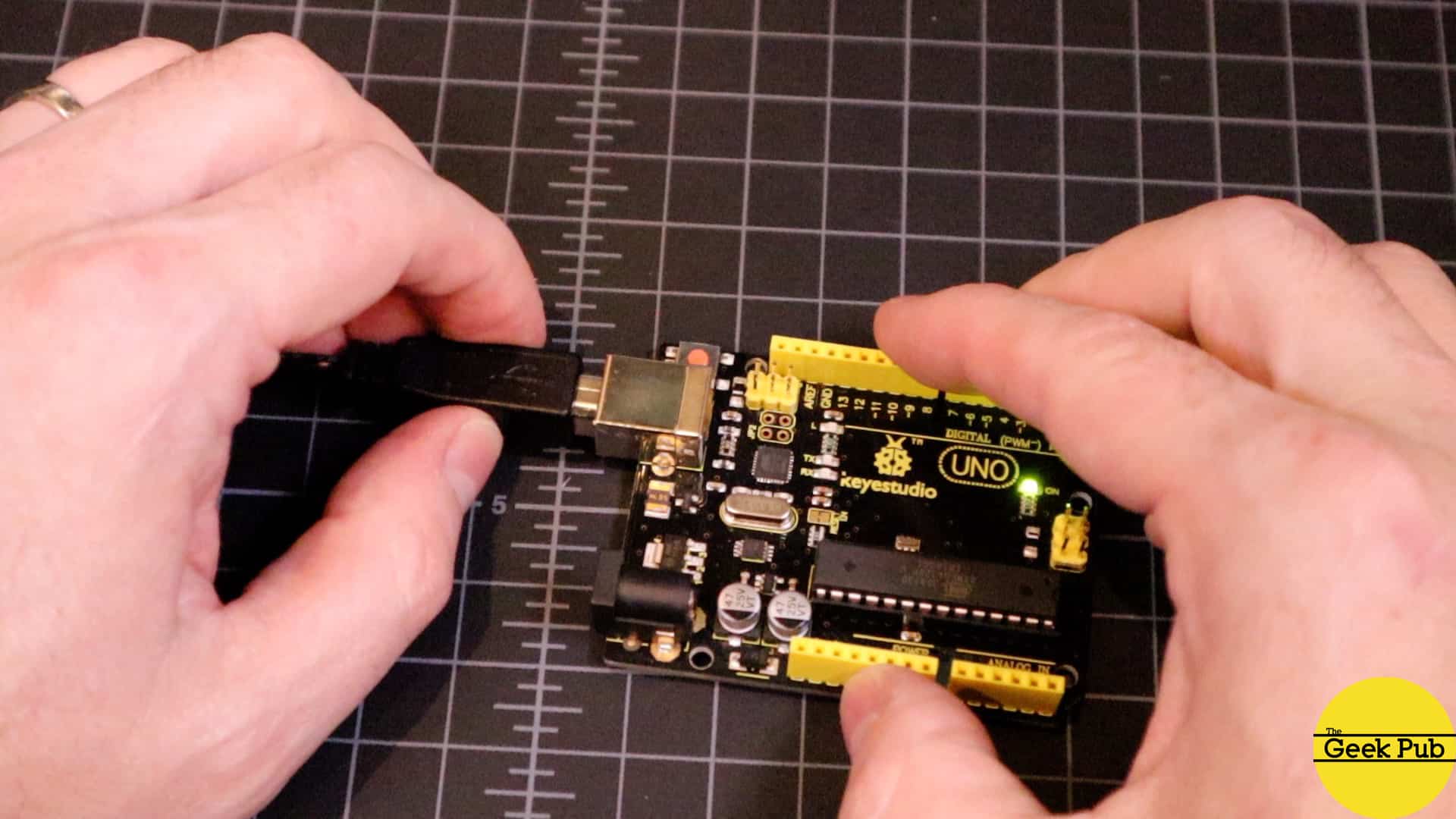
For example, if you have an Arduino Uno and you think the Oscillator crystal is bad, it’s super easy to check that on the oscilloscope. All you have to do to check the oscillator crystal is to measure it with the scope. First, connect the ground lead to any ground on the arduino. The closer electrically to the oscillator, the more stable the signal will be.
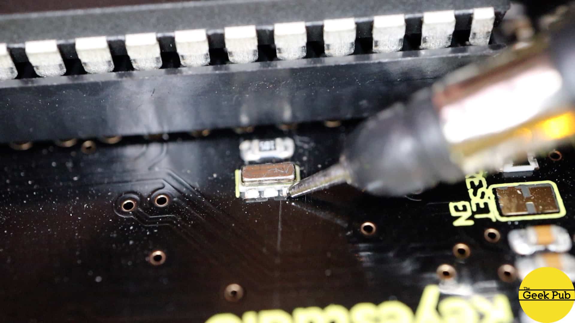
Now using the oscilloscope probe with the spring hook removed, use the tip of the probe to touch the solder pad on the output side of the crystal. You should see a 16Mhz oscillation on the oscilloscope. If you see any other value, it’s likely that the crystal needs to be replaced.
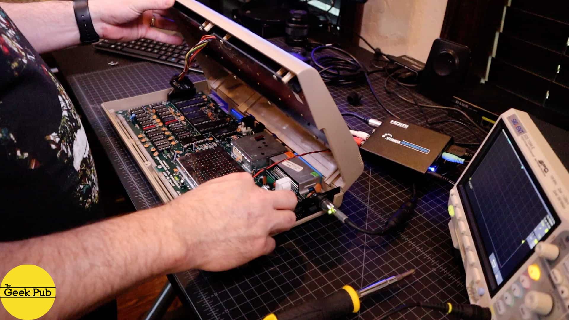
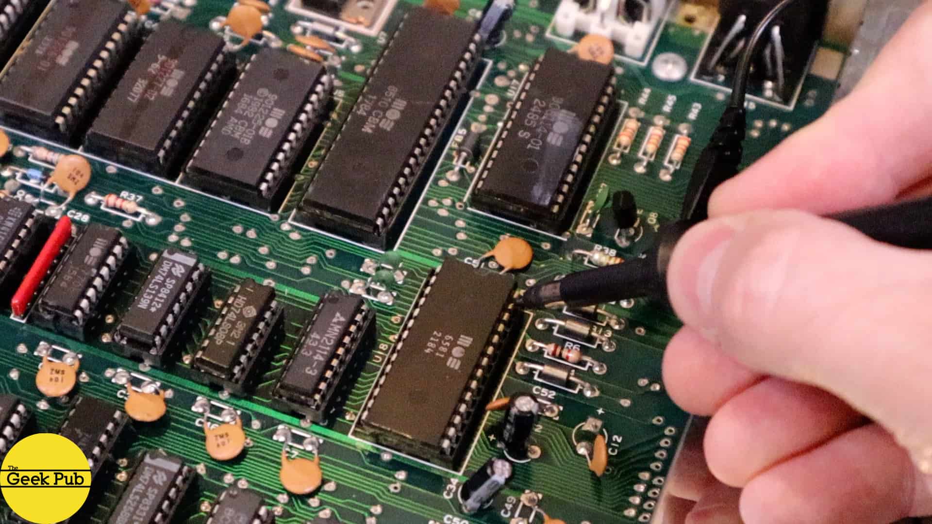
What if you suspect there is a problem with the SID chip in your trusty Commodore 64? You can check that with an oscilloscope!
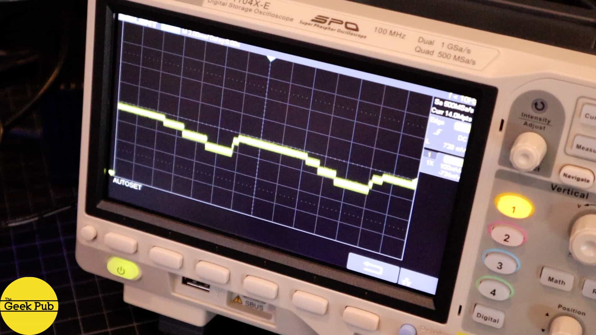
Carefully open the Commodore 64 making sure to disconnect the LED light so it doesn’t get hung on anything. I just used FB64 to mount the Standing Stones disk image and load the game. It’s got some pretty cool intro music we can use. Now, just touch the probe pin to the SID chips output line, pin 27 and you should see some fantastic waveforms represented on the oscilloscope’s display that seem to match the music you hear!
I hope you enjoyed this oscilloscope tutorial article and video. If you have any questions, leave a comment and we will do our best to help you out!


4.5
Great video Mike! Thanks for this!
4.5
I never knew I needed an oscilloscope, but damn now I need one!!!! P.S. I loved Standing Stones. One of my favorite retro games!
Wow. You know I have been seeing scopes in movies and TV shows for decades and honestly never really had any idea what they hell they did. Makes sense! Loved the video by the way, even old farts like me could understand it.
This is the best oscilloscope tutorial hands down! Thanks Mike!
0.5
J’ai constaté quel que chose d’extrême ment grave appler moi de toute urgence je vous explique tout par téléphone SOS Tel : 4188732020