Blog
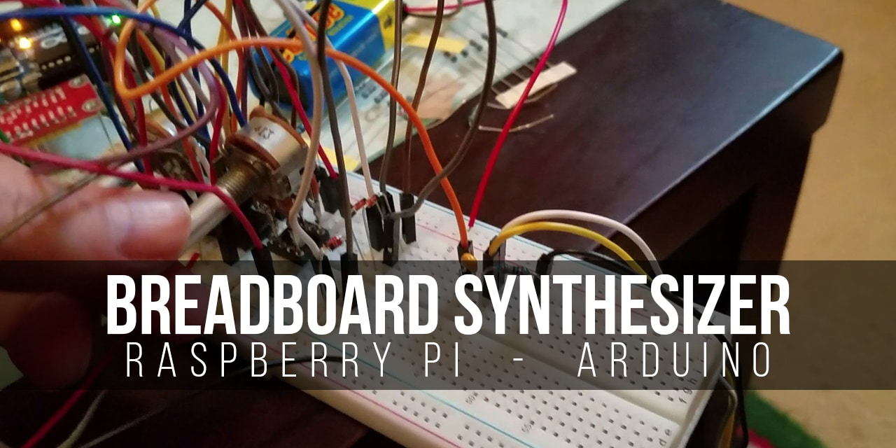
Building a Breadboard Synthesizer With a Raspberry Pi and an Arduino Uno
There’s a lazy stereotype about middle-aged men that says that all we want to do is tinker with our gadgets. I’m doing very little to challenge it, which I guess is how I came to weather the pandemic by trying to build my own
While I’m still very much still discovering things, what I’ve got on my desk right now is exactly the sort of thing that a guy like me would have loved to have been shown just 6 months ago.
Watch the Raspberry Pi Synthesizer Video
Before starting to build a breadboard synthesizer and following the instructions below, take a minute to watch this video to see what it looks like and sounds like!
It involves using a
I’m calling this
This is really meant for the beginners out there, who are stuck deciding where to start. If it looks a bit long, that’s not because it’s a hugely complex project, but because I’ve taken the time to break things down into the simplest steps that I reasonably could. If you’ve already been doing synth DIY for a while, it’s probably far more detail than you really need.
I’ll assume that you can tell a capacitor from a resistor and that you’ve blinked some LEDs before, but you don’t need to be much further than this. (And if you’ve not even blinked an LED yet? Don’t worry, the Geek Pub has you covered for Arduino and for
For sake of length, I can’t explain every part of every single line of code. If you feel like you’re copying and pasting things you don’t really understand.. well, that’s how I started off too.
Just be aware that code is fussy and that all the capitals, punctuation and spacing can matter. At the very end, I’ll link through to some resources that can help you further.
Let’s make some beeps!
Steps to Build a Breadboard Synthesizer
1. Gathering Your Supplies: The Parts List
2. Setting Up the Arduino Uno as a Wavetable Synthesizer
3. Controlling the Synthesizer Using UART Serial
4. Adding MIDI Functionality
5. Adding an Analogue Filter
6. Where to Next?
Parts List for this Project
If you don’t already have all the components needed for building a breadboard synthesizer, here’s a handy parts list for this project. If you use these links, they cost you nothing, but we get a small commission.
- Any Raspberry Pi with multiple USB ports
- All the usual fixings like a power supply, keyboard/mouse, and Micro SD-Card
- An Arduino Uno
- A solderless breadboard
- 1X TL074 quad op amp
- 3X 10nF ceramic capacitors
- 3X 2µF ceramic capacitors
- 1X 1k resistor
- 1X 6.8k resistor
- 1X 10k resistor
- 2X 200k resistors
- 1X 100k linear mono potentiometer
- 1X 100k linear stereo potentiometer
- 6X signal diodes (1N4148 or similar)
- Wires or jumper leads
- Powered speakers with a way to connect to the breadboard (see below)
This guide is written to work on
Build a Breadboard Synthesizer: Selecting Potentiometers
I’m won’t sugar coat this. Placing pots in a breadboard and getting them to stay there can be a pain in the rear!
Even when you find a pot with terminals correctly spaced, the terminals themselves are often still not the right size. You can jam them in to successfully close a circuit, only to find they pop out when you adjust them.
The stereo pot makes things more difficult again because it also has to straddle over the notch in the center of the breadboard. I’ve dealt with this by soldering something to the terminals. I used an IC socket, because I had one lying around.
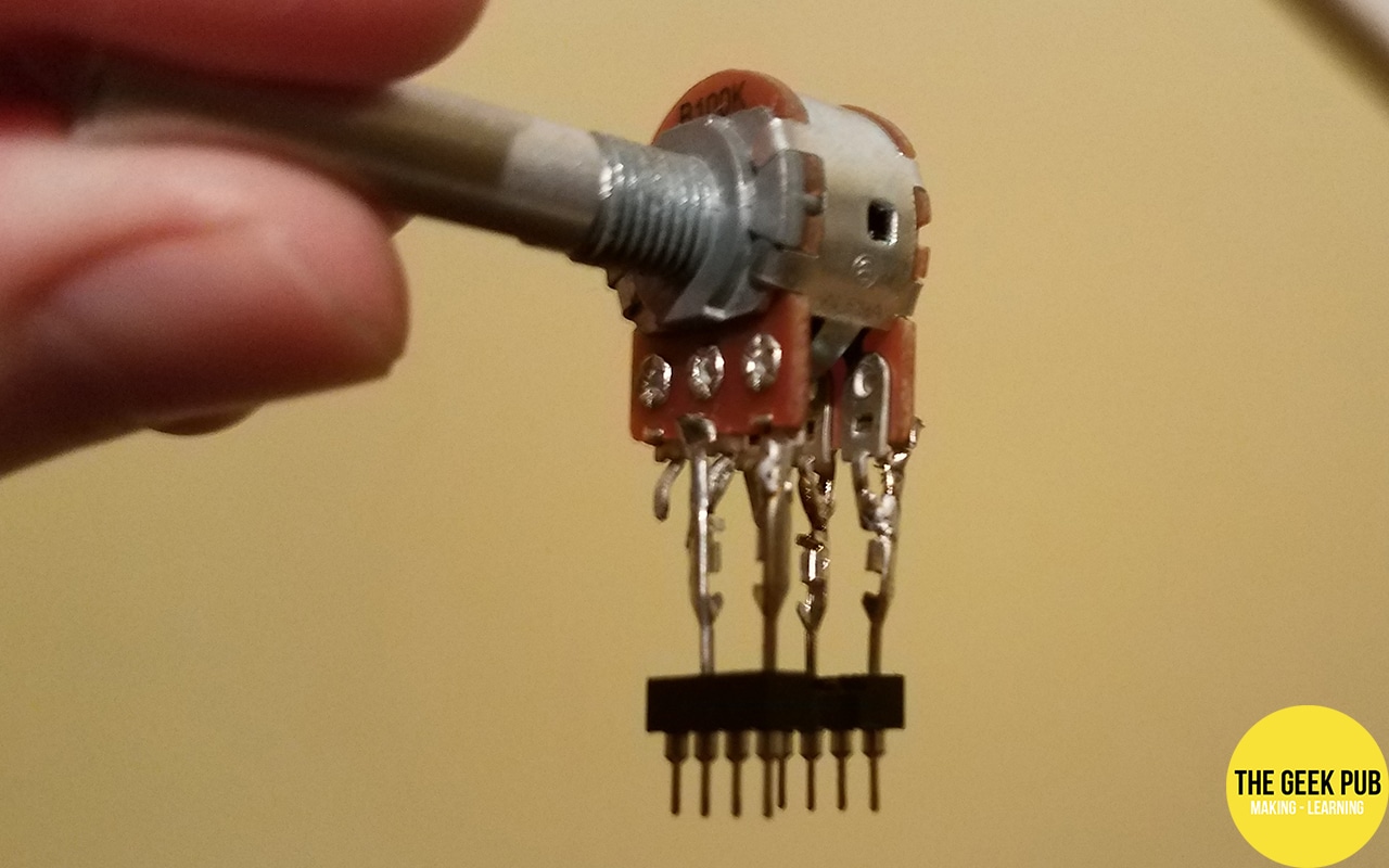
This has the additional benefit of making a bit more clearance between the shaft and the breadboard row directly beneath it. This makes it much easier to connect a jumper lead to the wiper.
You’ll see that I’ve only connected two terminals on each side here. That’s fine for this particular project where we build a breadboard synthesizer; we’ll use this stereo pot as a pair of variable resistors and the other terminal won’t be connected to anything.
Don’t Use Your Best Speakers!
Look, it’s unlikely that you will blow any speakers while building your
Still, use something expendable while you’re mucking about. That way, if you connect a thing to a thing only to find out that it was definitely the wrong thing, at least you didn’t do it to your mum’s component hi-fi.
You can use a mono speaker, like an old practice amp. You could also use an old pair of computer speakers or a beat up old hi-fi. Be sure it’s a powered device and that it has some kind of analogue input.
If you don’t already have anything like that, look for something for ten dollars in the second-hand shop or on Facebook Marketplace.
Connecting Your Speakers to the Breadboard
Whatever kind of connector your speakers use as you build a breadboard synthesizer, they’re not going to plug straight into a breadboard itself. I’ve dealt with that by soldering jumper leads to a 3.5mm stereo socket from my local electronics shop.
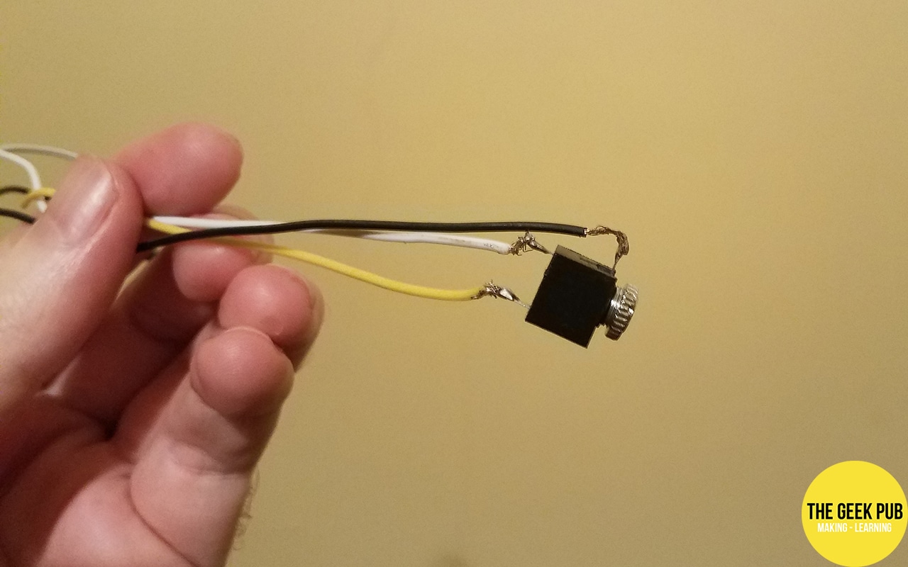
If you hate soldering, you might rig up something similar with alligator clips or by wrapping wires around a jack. But honestly, this is a really easy job and if your soldering sucks, it’s an ideal chance to practice.
Installing the Arduino IDE on the Raspberry Pi
You don’t have to use your
Setting up the Arduino Uno as a Wavetable Synthesizer
Thankfully, we don’t have to code the whole synthesizer from scratch. A talented maker called DZL has published a pair of wavetable synthesis libraries for the Arduino.
All we need to do is install these libraries to the IDE and write a quick sketch to control them from the
What is a Wavetable Synthesizer?
Wavetable synthesis is a technique where the shape of each basic waveforms is stored in memory as a table of voltage values. Because only one cycle of each waveform needs to be stored, it’s really memory-efficient.
This one technique allows for an incredibly versatile range of waveforms. You can even edit the tables file to add your own shapes. Compare this to analogue synthesizers, where adding a different wave shape can mean you need a completely new circuit.
This particular wavetable synthesizer works by using PWM on pin 11 of the Arduino Uno. We connect this pin to a simple low pass filter, which smooths the rapid flickering of the PWM pin on into a real analogue voltage that corresponds to the duty cycle of the PWM.
By cycling through the different voltage levels, we can plot out wave shapes. By changing the speed we move through them, we vary the frequency of the signal, which changes the pitch of the sound.
This particular implementation offers 8 bits of dynamic range. That falls well short of high fidelity audio, but it will suffice for simple waveforms. It has loads of character too: the same 8 bit sonic signature heard in so many 80s and 90s video games.
Installing the synth libraries
Browse to https://github.com/dzlonline/the_synth and then click on the button up the top that says “Code”.
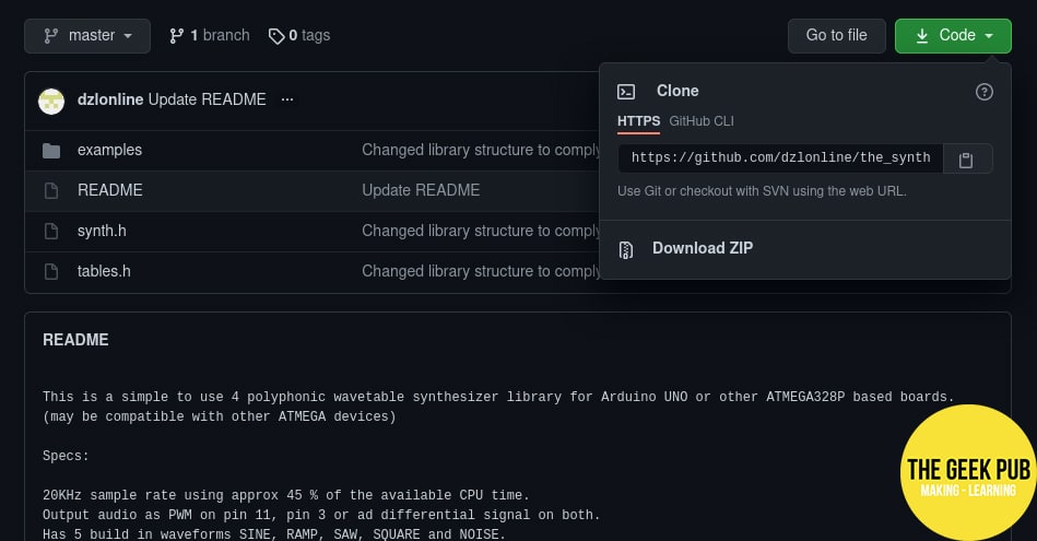
Select Download Zip and then save.
In the Arduino IDE, click the Sketch menu, hover over Include Library and select Add .ZIP library…
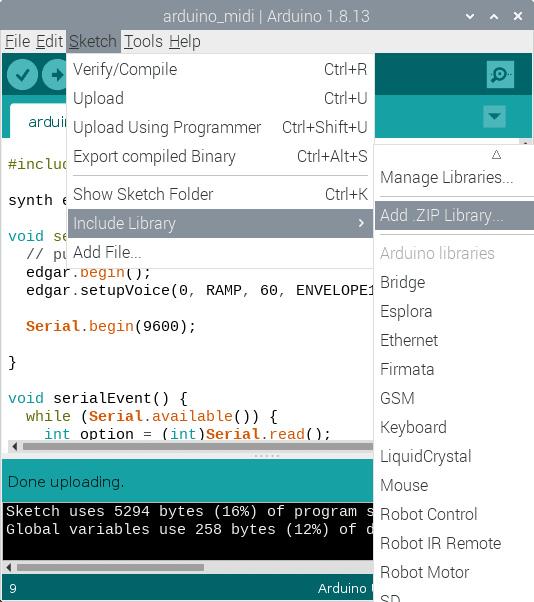
Find the_synth-master.zip in your Downloads directory, select it and press OK. You’ve now installed it to your Arduino IDE 🙂
Installing the any hertz demo
This library comes with a few simple example sketches, ready to go. Let’s start with any_hertz, which just loops through four tones indefinitely.
That’s a good enough starting point to make sure the wiring is right. We can develop it into a more interesting program soon.
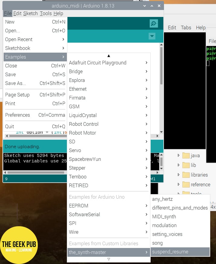
So open the File menu, select Examples and then the_synth-master and open the any_hertz sketch. Upload this to your Arduino Uno.
Connecting the Arduino Uno to the breadboard
Setting up an Arduino Uno for wavetable audio doesn’t require of components – just two resistors and two capacitors. One resistor and capacitor pair will form a passive low pass filter, smoothing the PWM pin’s flickering into a true analogue voltage.
The other pair is used for coupling. It passes the audio signal to the next circuit, blocking any DC voltage that could arise from using two different power supplies.
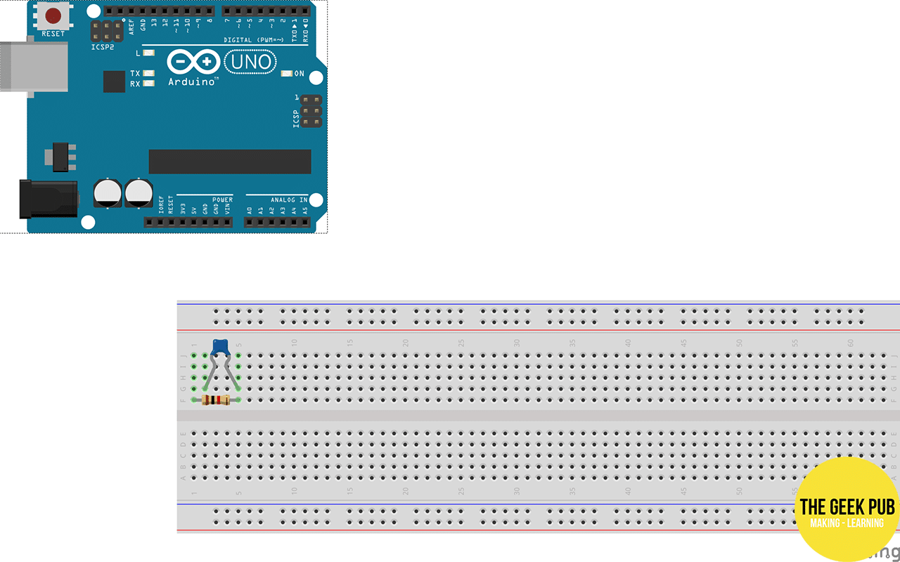
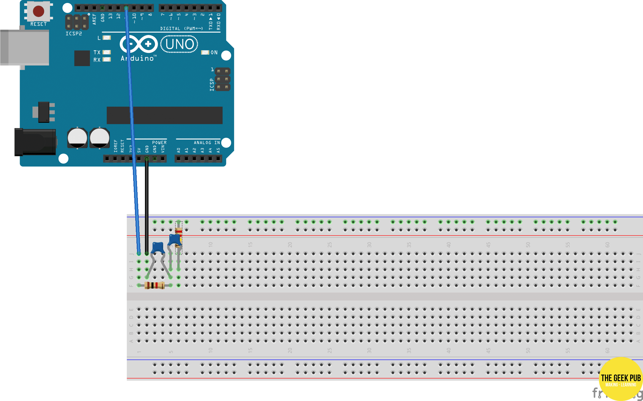
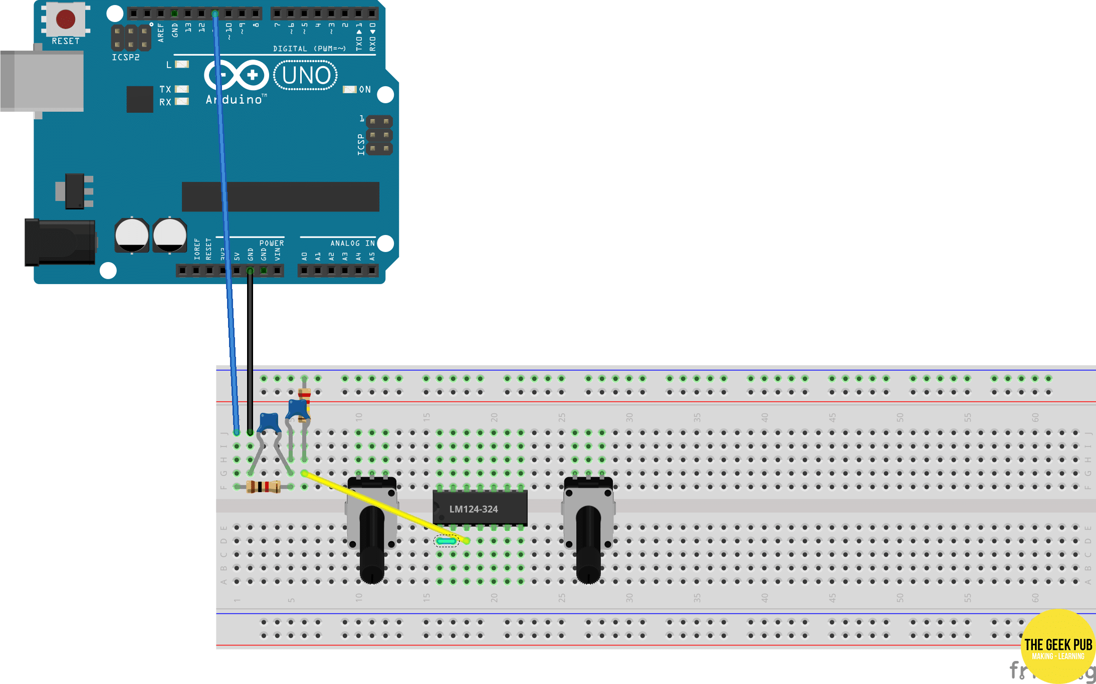
Let’s start by building the low pass filter in the top left corner of the breadboard. Place the 1k resistor to the 1st and 5th columns, and the 10nF capacitor to the 2nd and 5th columns, like this:
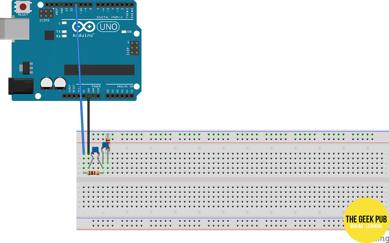
Now connect the Arduino Uno. Wire pin 11 to the 1st column, and a ground pin to the 2nd column.

That’s our low pass filter done. Easy, hey? 🙂
Now for the coupling capacitor. Connect a 1µF capacitor to the 5th and 6th column, and a 200k resistor to the 6th column and to the negative rail.
Connect your speakers to the synthesizer by connecting the signal wire(s) to the coupling capacitor and the ground wire.
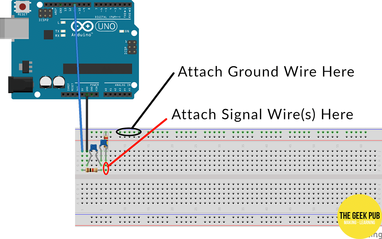
If everything’s wired correctly, it beeps. Hooray!
Controlling the Synthesizer Using UART Serial
On first hearing these four tones sound a glorious fanfare to your success in building a breadboard synthesizer. As this sensation fades, it sounds a bit boring.
What would be much more interesting is a synthesizer we can control and interact with.
When I first attempted this, I wanted to use the I2C protocol. On paper, it looked amazing. With just two pins, you can send instructions to dozens of peripherals. That’s lots of room to extend this configuration.
When I tried it, it worked flawlessly for a minute or two, then produce a hardware error that left the Arduino Uno completely unresponsive until it was reset. D’oh!
UART is limited to 2 way communication, but still leaves all the GPIO pins and hardware peripherals for other things. The bit that’s super easy right here is that it’s already physically connected by USB. We just need to write some code that describes how to use this connection.
Configuring the Arduino Uno
Next up on our
[code language=”cpp”]
Serial.begin(9600);
[/code]
Next, we need to write a function called void serialEvent(). The Arduino IDE knows from this name to call it every time a message arrives. It’s important to spell and capitalise it exactly or it won’t run.
Let’s keep it simple and read a single byte. This gives us a range of integers from 0 to 255, each of which can be used for a different instruction.
If we use bytes 0 to 127 to play notes, this matches the MIDI specification. This will be useful later.
In 440hz concert pitch, the formula to convert a MIDI number to a frequency is:
frequency = 440 × 2(number−69)/12
If you’re at all unsure what’s going on there, it’s to do with how octaves and equal temperament work. That’s a bit much to get bogged down in right now.. but by all means, nerd out on the links!
We can write this in C as:
[code language=”cpp”]
float pitch = 440.0 * pow( 2.0, ((float)midinote – 69.0) / 12.0);
[/code]
It’s also musically useful to have a stop instruction for pauses and rests. Let’s use 128 for this.
When we put all this together using switch…case statements, we get this:
[code language=”cpp”]
void serialEvent() {
while (Serial.available()) {
int option = (int)Serial.read();
switch (option) {
case 128:
edgar.setFrequency(0, 0.0);
edgar.trigger(0);
break;
case 0 … 127:
float pitch = 440.0 * pow( 2.0, ((float)option – 69.0) / 12.0);
edgar.setFrequency(0, pitch);
edgar.trigger(0);
break;
}
}
}
[/code]
Now that it’s set up to play notes based on incoming instructions, let’s remove the lines of code from the loop function. Don’t remove the loop function completely. The Arduino IDE expects to find it or it won’t compile, but it’s happy for it to be empty.
[code language=”cpp”]
void loop() { }
[/code]
It also might be a good idea to change the waveform from a triangle to something with a bit more harmonic content, like a ramp or a square. This will mean that the resonant filter we build later will have more high frequencies to play with.
So find the line that says
[code language=”cpp”]
edgar.setupVoice(0,TRIANGLE,60,ENVELOPE1,127,64);
[/code]
and change it to:
[code language=”cpp”]
edgar.setupVoice(0, RAMP, 60, ENVELOPE1, 127, 64);
[/code]
Your full Arduino sketch should look like sort of like this:
[code language=”cpp”]
#include <synth.h>
synth edgar;
void setup() {
edgar.begin();
edgar.setupVoice(0, RAMP, 60, ENVELOPE1, 127, 64);
Serial.begin(9600);
}
void serialEvent() {
while (Serial.available()) {
int option = (int)Serial.read();
switch (option) {
case 128:
edgar.setFrequency(0, 0.0);
edgar.trigger(0);
break;
case 0 … 127:
float pitch = 440.0 * pow( 2.0, ((float)option – 69.0) / 12.0);
edgar.setFrequency(0, pitch);
edgar.trigger(0);
break;
}
}
}
void loop() { }
[/code]
Compile it and upload to your Arduino Uno.
Build a Breadboard Synthesizer: Configuring the Raspberry Pi
I’ve always seen Python as the easy way to program – an ideal choice for beginners and people in a hurry. C is at the other end of that spectrum: a precise and exacting language for folks like Linus Torvalds.
It turns out though, that once we start working close to the hardware level, a lot of the hidden little things in Python can suddenly become a headache.
For instance, did you know that, if you want to turn one of Python’s standard two byte integers into a single byte integer, you have to put in a list first? I didn’t. If you just type bytes(128), you get 128 null characters in a row, so it has to be bytes([128]).
The vexing thing is that it’s really hard to figure this out from the official documentation. It kind of all relies on you stumbling across a forum post from somebody who had the same problem six years ago.
C has its own ways of being fussy. But at least, if you really want an int or a byte, you can just ask for one and it gives it to you.
I digress.
Open a terminal window on your
[code language=”bash”]
python3
[/code]
To work with the serial port, we use the pre-installed serial module, which is conveniently called serial. Let’s import it.
[code language=”python”]
import serial
[/code]
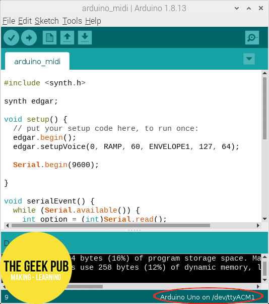
Now we need to use this to connect to the serial port. To do this, we need to know where Linux sees it. The Arduino IDE makes this easy because it happily just tells us. It’s in the bottom right corner of the code editor and will look something like /dev/ttyACM0 or /dev/ttyACM1.
Once you know where the port is, you can create an object to access it in Python with a command like this:
[code language=”python”]
arduino = serial.Serial(‘/dev/ttyACM1’, 9600, timeout=1)
[/code]
This Serial object has a write method we can use. Remembering that we have to convert the integer to a byte, we can write to it like this:
[code language=”python”]
arduino.write(bytes([70]))
[/code]
Hey, did that play a note? Now try different numbers.
[code language=”python”]
arduino.write(bytes([50]))
arduino.write(bytes([42]))
arduino.write(bytes([69]))
[/code]
What about rests and pauses? In our Arduino sketch, we set 128 as the byte to lift the note. Let’s see what happens when we write that to the serial port.
[code language=”python”]
arduino.write(bytes([128]))
[/code]
With this, we can play any note and none at all.
Adding MIDI Functionality
If you just stopped here, you could to tell your friends you built a synthesizer and technically it would be true.
But this is a very cumbersome synthesizer, needing lines and lines of code to play even a simple melody. This is not a very intuitive or inspiring way to make music.
What would instantly make this more musically useful is the Musical Instrument Digital Interface, or MIDI. This is a standard way for computers, synthesizers and other audio devices to send and receive messages about which notes to play and when.
The good news is that your
All we need then is to connect two things to ALSA: something to send MIDI messages, and something else to receive them.
To generate the MIDI messages, we can use a range of music programs. I’ll take you through installing Seq24, a simple MIDI sequencer.
To handle these messages, it’s very easy to write our own script in Python. We can open a MIDI port using the Python module Mido, and then use these MIDI messages to write bytes to the serial port as we did before.
Installing Seq24
Keep open the terminal window running the Python interpreter. We’ll switch back to it soon.
Open another terminal window to install Seq24. You can find it in the
[code language=”bash”]
sudo apt update
sudo apt upgrade -y
sudo apt install seq24 -y
[/code]
Keep this terminal window open.
Installing Python modules
We need the Python package manager to install Mido. It’s usually installed by default, but if you don’t have it, you can type:
[code language=”bash”]
sudo apt install python3-pip -y
[/code]
Mido also relies on another Python module called python-rtmidi. We can install these together using the one command.
[code language=”bash”]
sudo pip3 install python-rtmidi mido
[/code]
Close this terminal window and switch back to the Python interpreter.
Writing Our First Mido Script
Now that Mido is installed, we can import it into Python in the usual way.
[code language=”python”]
import mido
[/code]
Mido to open a virtual port, which Linux
[code language=”python”]
port = mido.open_input(‘wavetable’, virtual=True)
[/code]
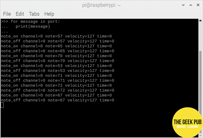
We can watch what’s going into the port by writing a loop, like this:
[code language=”python”]
for message in port:
print(message)
[/code]
Press enter on a blank line to run the loop.
What happens next will look a bit uneventful. It has nothing to say until the MIDI messages start arriving. So let’s make some!
Connecting Seq24 to the MIDI Port
Open Seq24 from the Application menu in the top left corner of the desktop.
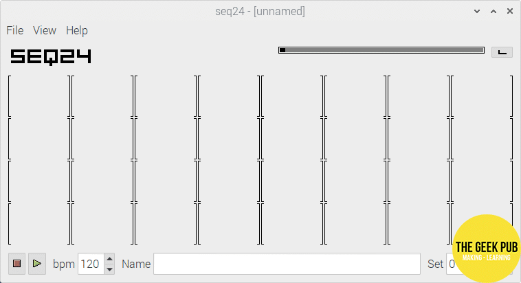
Here you’ll see the main pattern editor for Seq24. Each of these containers holds a sequence. Right click on one and select “New” and you can edit it.
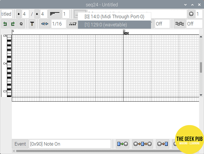
Near the top right is a field you can click to select which MIDI port to use. Click on it and you’ll see the wavetable port we created with Mido. Go ahead and select it.
Now left click a few times on the piano keys on the right side of the sequence editor. Then switch back to the Python interpreter. You should see note_on and note_off messages displayed for the notes that you clicked.
We’re nearly there. Let’s turn these MIDI messages into sounds.
Parsing MIDI Messages With Mido
We can turn these messages into beeps with a loop that’s not very much more complicated to the one we just wrote. Instead of just printing the message, we want to check whether it is a note_on or a note_off message – any other type of MIDI message, we can just disregard. The note_on message can then be parsed for which note to play, while a note_off message can be just turned into a pause instruction.
Start by pressing ctrl+C to exit the loop. Then write another one that goes like this:
[code language=”python”]
for message in port:
if message.type == "note_on":
arduino.write(bytes([message.note]))
if message.type == "note_off":
arduino.write(bytes([128]))
[/code]
Press enter a second time to run the loop.
Now when you use the sequencer, you should hear it play.
For more on how to sequence in Seq24, click here.
Adding an Analogue Filter
So far, we haven’t ventured very far from computer based synthesis. So let’s get right down and dirty with some analogue electronics.
There’s a low pass filter on the board already. This is there as a necessity: without it, the flickering of the PWM wouldn’t be shaped into analogue voltages at all.
Now we’re adding a filter for musical reasons – a design taken from Moritz Klein’s excellent DIY VCF series.
This gives us an adjustable cutoff frequency. By turning the potentiometer, we can control how much harmonic content comes through. This turns our one basic waveform into a whole palette of timbre, that can change as the music plays.
It also has a resonance control. Adding more resonance boosts the frequencies just below the cutoff frequency, making the sound a bit more nasal, and emphasizing the sweep of the moving cutoff.
If you turn the resonance up far enough, the filter will self-oscillate: it will produce a sine wave tone of its own at the resonant frequency.
About this Filter
As we build a breadboard synthesizer, let’s discuss the filter for a minute. This is a two pole, 12dB per octave active low pass filter. It’s built around two passive RC filters, buffered by op amp stages. The resonance works by connecting the filter’s output to the capacitor of the first RC filter. We can also add diodes to this feedback loop to clip the resonance. This tames the resonance while giving it a dirtier sound.
If you’re scratching your head at any of that, don’t worry. Moritz’s videos already explain how this circuit works so well that it would be silly to duplicate it.
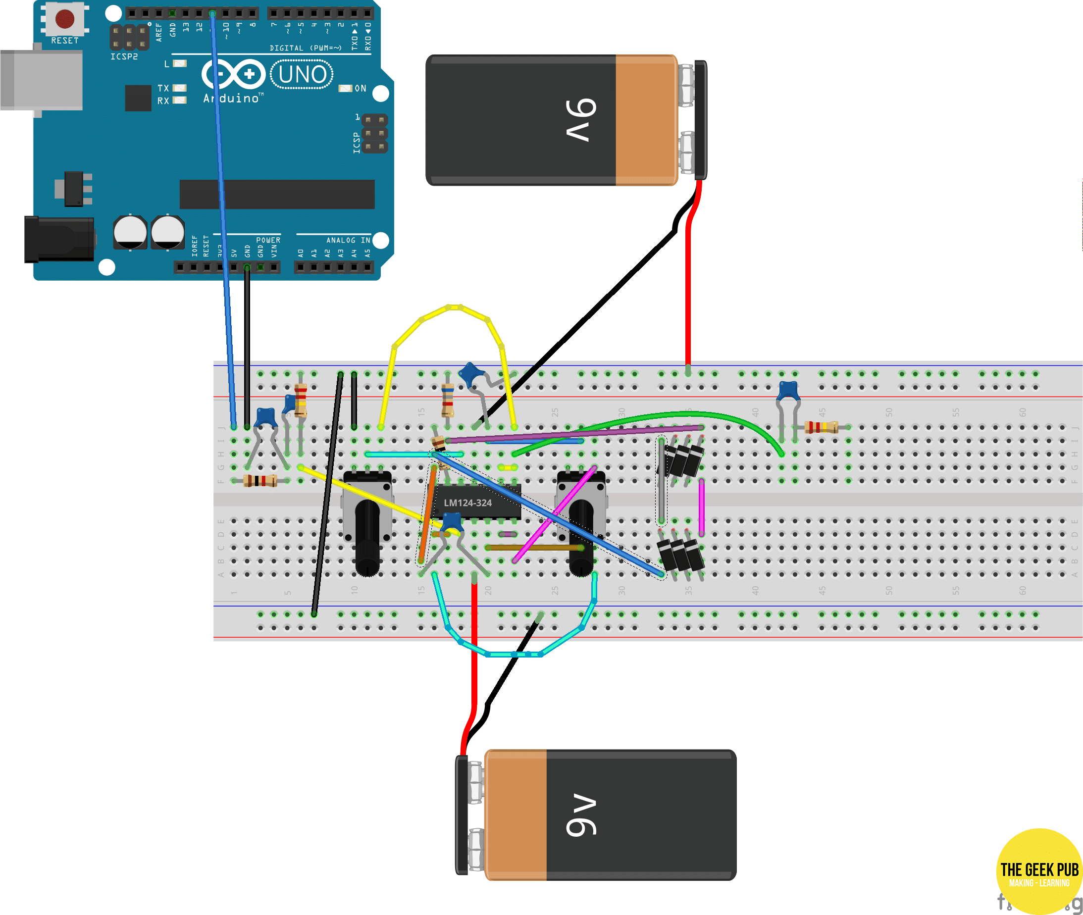
The only big thing we’ll do differently is that we don’t have the ±12 volt split power supply he’s using. Instead, we can build our own split power supply from two 9 volt batteries.
Compared to the 5 volt peak-to-peak signal from the Arduino Uno, this gives us plenty of headroom – we can skip the step about dropping the voltage down.
Additionally, if you’re totally new to op amps, you might also want to watch this explainer from EEVBlog.
It’s okay if you don’t have time for the videos; I’m not your dad and I can’t tell you what to do. Everything should still work fine by following these steps, you’ll just get more out of doing it if you understand what’s going on.
That’s enough background – let’s build this thing!
Buffering the Wavetable Output
First, disconnect the speakers from the breadboard.
Then place the pots and the TL074 quad op amp on the board. Put the mono pot just to the right of the coupling capacitor, then the IC, the stereo pot. Keep a couple of columns space between them for wiring.

Be sure that the little notch on the TL074 faces left so that the power pins are the right way around.
Now, we want to use one of the op amps to buffer the output from the wavetable synthesizer. Connect the coupling capacitor to the non-inverting input of the first op amp, then connect the inverting input directly to the output.
Our
We’ll start with the negative power pin, which is the middle pin at the top of the IC. Connect the negative wire to the negative power pin, and the positive wire to the ground rail at the top of the breadboard.
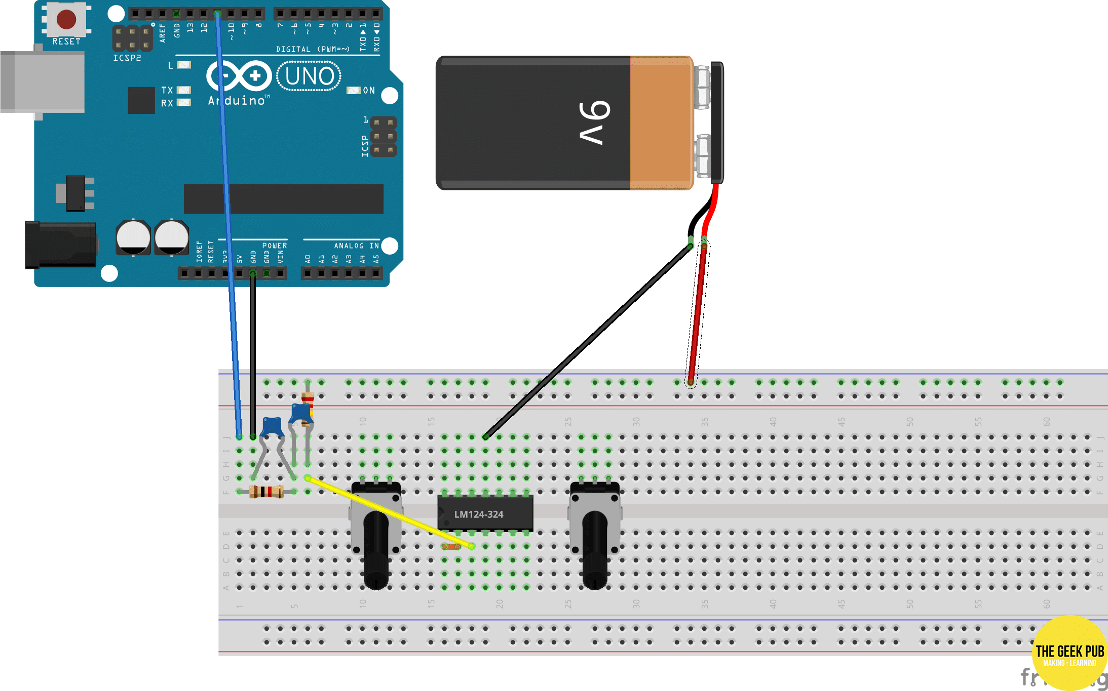
Then take your other battery and connect the positive wire to the positive pin on the bottom of the IC. Then connect the negative wire to a power rail at the bottom of the breadboard. Connect the power rails to complete the circuit.

It’s a good idea to have a listen as we build our
Leaving a bit of space for the clipping diodes, place a 1µF ceramic capacitor on the board. Then connect a 200k resistor to the right leg of the capacitor and to an empty column on the board.
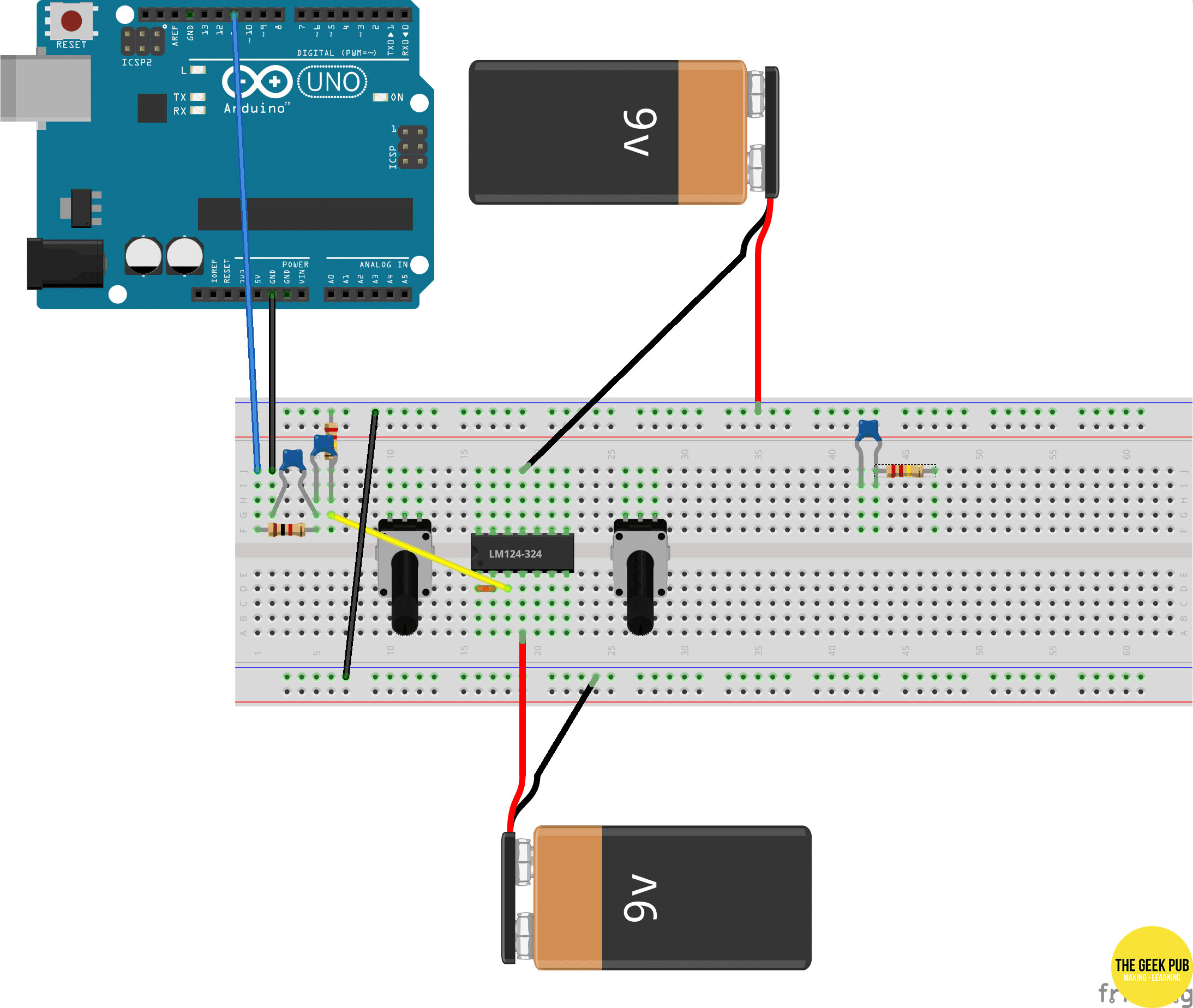
Connect the output pin of the op amp to the coupling capacitor. Then connect the signal wires to the coupling capacitor and the ground wire to the resistor, just like we did before.

Play something on the synthesizer and check that it works. It shouldn’t sound any different yet. Let’s do something about that.
Building the Filter Stages
Next up for building a breadboard synthesizer, let’s remove the wire between the op amp and the coupling capacitor, leaving the speakers connected.
Connect output of the op amp to one side of the stereo pot. Connect the other to the non-inverting input of the second op amp.

Now take a 10nF capacitor and connect one leg to the non-inverting input of the second op amp. Connect the other leg to the ground rail.

Connect the output to the inverting input on the second op amp to configure it as a buffer.

This is one pole of our two pole active filter complete. Now use the third op amp to build the same thing again.
Connect the output of the second op amp to the unused side of the stereo pot. Wire the other terminal of the pot to the non-inverting input of the third op amp and place a 10nF capacitor to the non-inverting input and to ground.

Connect the output to the coupling capacitor and congratulate yourself on building a 2 pole, active filter!

Play something on the
Adding Resonance as we Build a Breadboard Synthesizer
When building a breadboard synthesizer, you can do quite a lot with only a cutoff control. But, you know what’s a whole new toy to play with and only takes a few minutes to build? A resonance control! Let’s do this thing.
Connect the output of the the third op amp to the right terminal of the mono pot. Don’t remove the connection to the coupling capacitor, it’s fine as it is. Connect the left terminal of the pot to ground.

Now let’s connect the wiper terminal to the non-inverting input of the last op amp.

We don’t want to configure this as a buffer but as an amplifier. So, instead of wiring the ouput directly to the inverting input, connect them using a 10k resistor. Then connect a 6.8k resistor to the inverting input and to the ground rail.
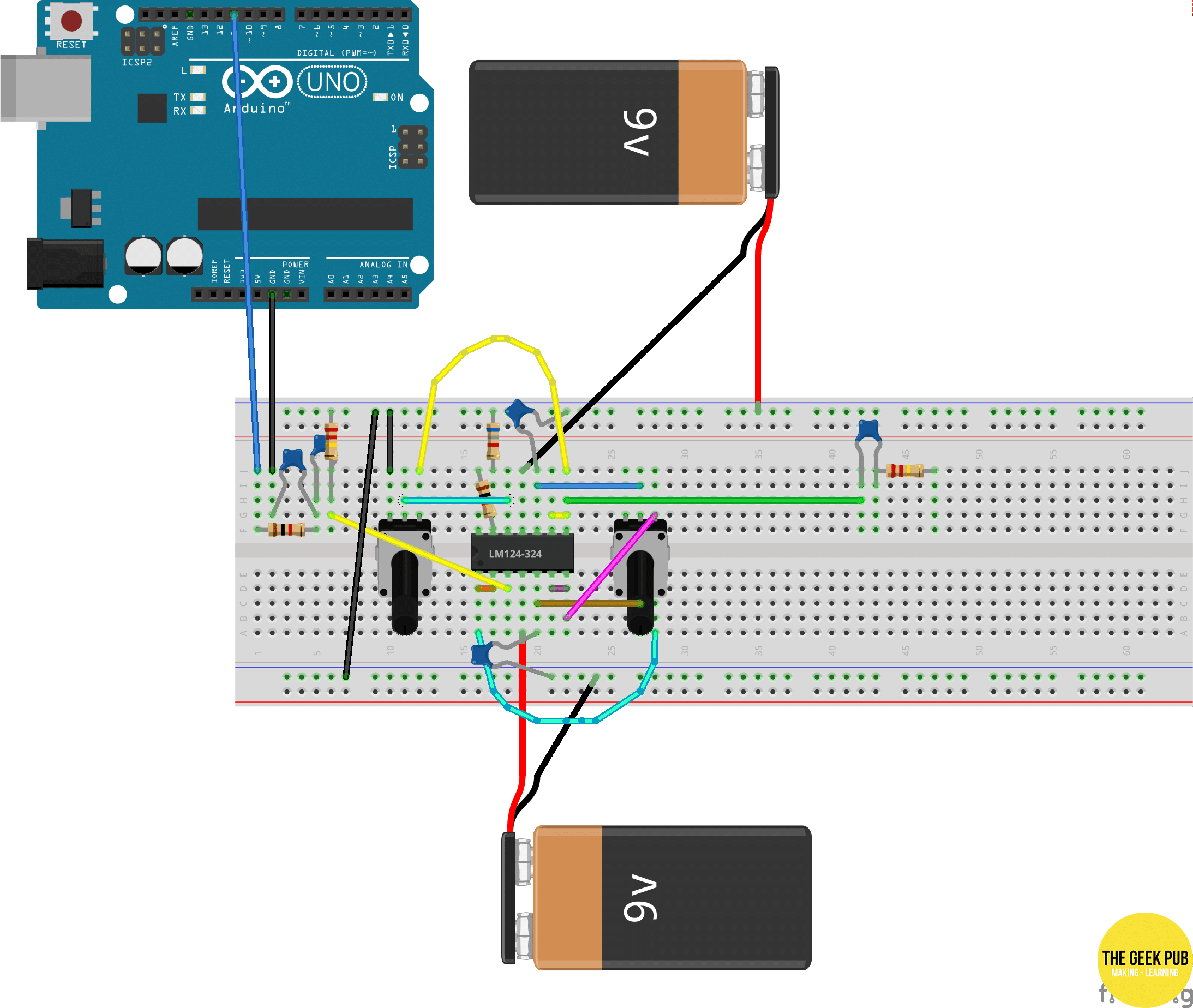
This is kind of the fiddly bit. We want to take the 10nF capacitor connected to the non-inverting input of the second op amp, disconnect one leg of it from the ground rail and then place that leg in an empty breadboard column in between the TL074 and the mono pot. Connect the output of the fourth op amp to that column too.

Now you have a working resonance control!
Try turning the cutoff knob with the resonance in different positions. Turn the resonance up enough and you will find a point where it becomes so dominant that this frequency takes over – it’s self-oscillating. You can then twist the cutoff pot to change the pitch of this tone.
Build a Breadboard Synthesizer: Adding Clipping Diodes
The last thing from Moritz’s video to implement in our
When you look at a diode, you will see a ring on one end. This marks the cathode – the side that connects to negative. The other side is the anode – the side that connects to positive. Using the spare space between the cutoff pot and the speaker connection, above the notch of the breadboard, place a row of three diodes with the cathodes pointing right. Then in the space below the notch, place a row of three diodes with the cathodes pointing left.

Now connect these rows together so that the anode end of each row connects to the cathode end of the other.

Connect one end of this pair of rows to the output pin of the fourth op amp. Connect the other end to the inverting input.
Yes, the TL074 is a bit cluttered now. But you have diode clipping! Play something on the synthesizer and you’ll notice the resonance is less dominant but also kind of dirtier too.
Don’t Be Afraid to Mess Around With Clipping Diodes
I personally prefer enjoy the sound of four diodes instead of six. This reins the resonance in a lot more; even when it’s turned all the way up, it still only sits on the edge of self-oscillation. It also sounds dirtier and gnarlier.
You can also pay with asymmetric clipping. That’s where you clip the top and bottom of the waveform differently by using a different number of diodes on each row, or even only using a single row. That’s a cool sound too.
You may even decide you prefer the sound of no diode clipping at all. That’s the great thing about DIY: once you’ve learnt the why and the how, you can make what you want.
Disconnecting From Power
If you’re going to leave this
Build a Breadboard Synthesizer: Where to Next?
If you’ve gotten this far, congratulations on building your first breadboard synthesizer! So what now? Well, it’s up to you.
Here’s a few ideas:
- You might want to expand the switch…case section in the Arduino sketch to allow you to select different waveforms. You might also expand the Python loop to control this using the MIDI protocol’s control change messages.
- You could also look at adding voltage control to the filter, using either vactrols or transistors. You could then program envelopes and LFOs.
Here’s another idea:
- Try putting another PWM pin on the board and slightly detuning this synth voice by a few hertz to really fatten the sound. You could even assign different waveforms to each pin to get more complex sounds.
For more ideas of what to explore next, check out the resources at Synth It Yourself.
About the Author
 James Mawson is a technology copywriter and content marketer from Melbourne, Australia, freelancing for tech businesses large and small from all corners of the world. He’s also launching Synth it Yourself, a resource for DIY synthesizer hobbyists. In his spare time, he’s a keen Linux and