Blog
The Best GPIO Tutorial for Raspberry Pi that We Could Write
You can do a lot with a
Below, you’ll find an introduction to the concept of GPIO in general and to the
What’s with these GPIO pins, anyway?
If you already have a little familiarity with the
When it comes to the GPIO pins themselves, things are pretty much exactly what they appear to be. GPIO pins are little metal pins that can transmit signals but which are not “committed” (that is, not connected to anything outside of the circuit board they’re attached to — until you come along and change that, of course). Nothing in the GPIO pins themselves is specific to any particular sort of signal — hence the “general-purpose” part of the name — but that doesn’t mean that we can connect any old wire to them. The circuitry that GPIO pins end up attached to will have something to say about that! Depending on the board, these identical pins can serve very different purposes.
Let’s take a look at a
Why? Because computers are delicate things, and because the signals that we send when we’re working with circuitry are electrical signals. Let too much juice flow through the wrong pin, and you’ll trash your
Again, the pins are perfectly happy with whatever job they are assigned, but the circuit board (in this case, the
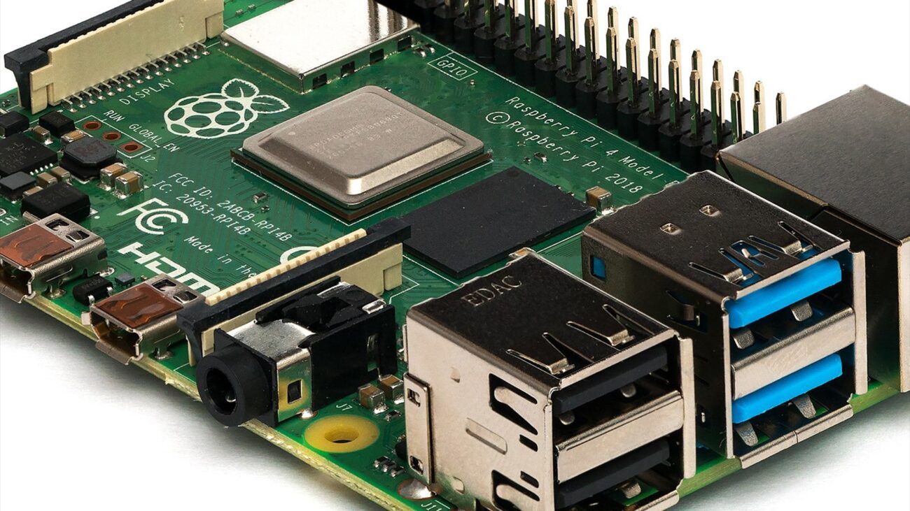
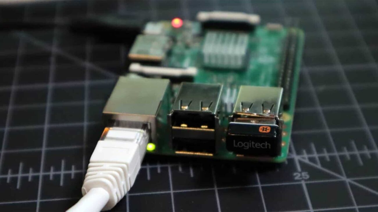
The Raspberry Pi ‘s GPIO pins
Okay, let’s talk
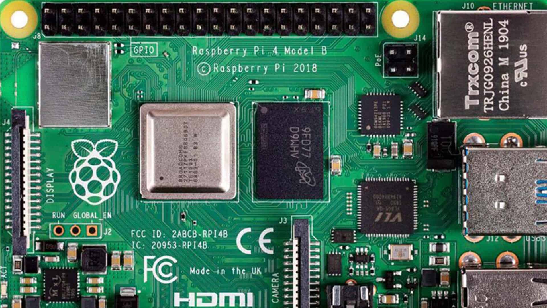
Every member of the current
Here’s a map of what the 40 pins on modern
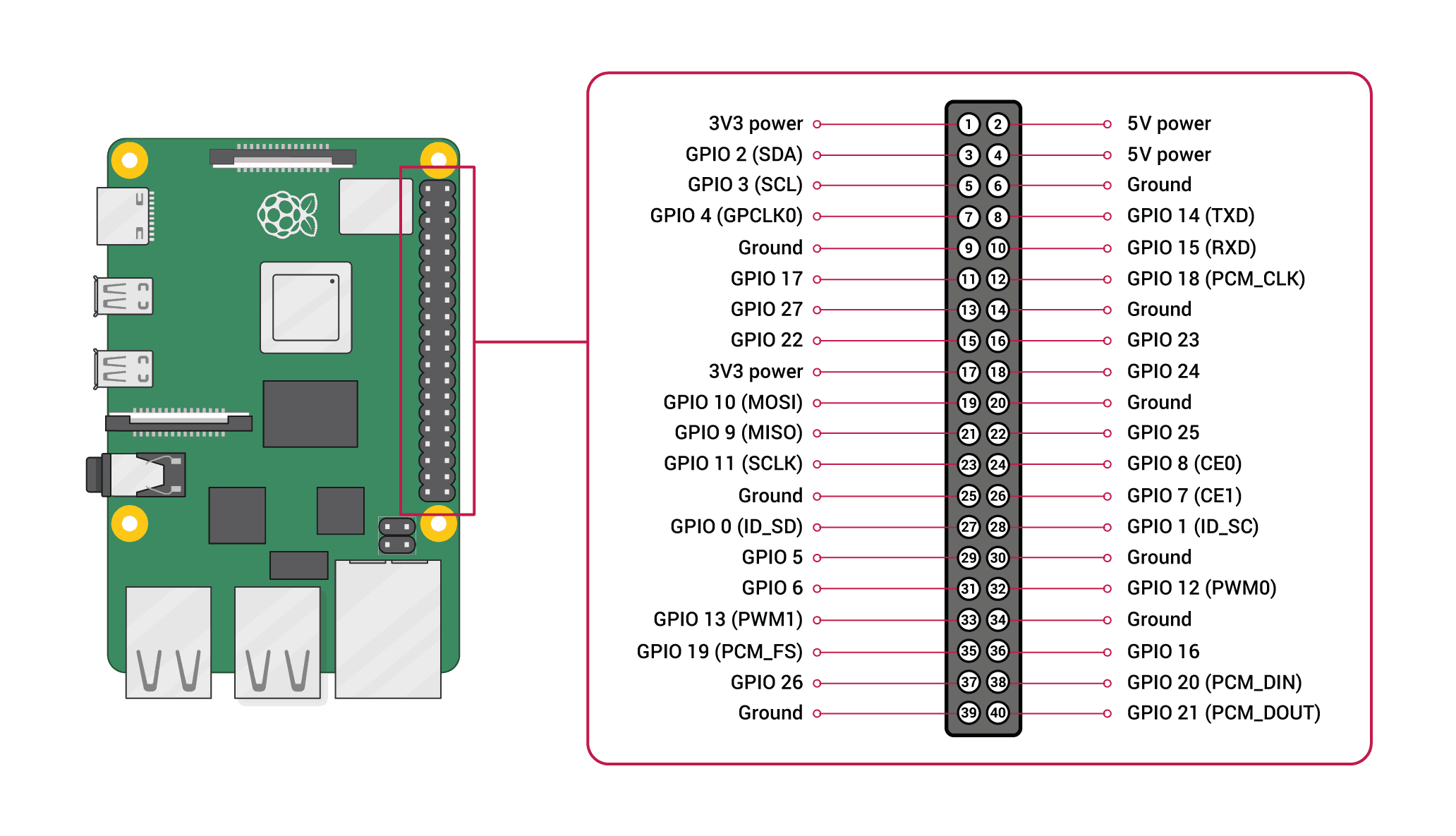
Image credit:
If you have one of the older
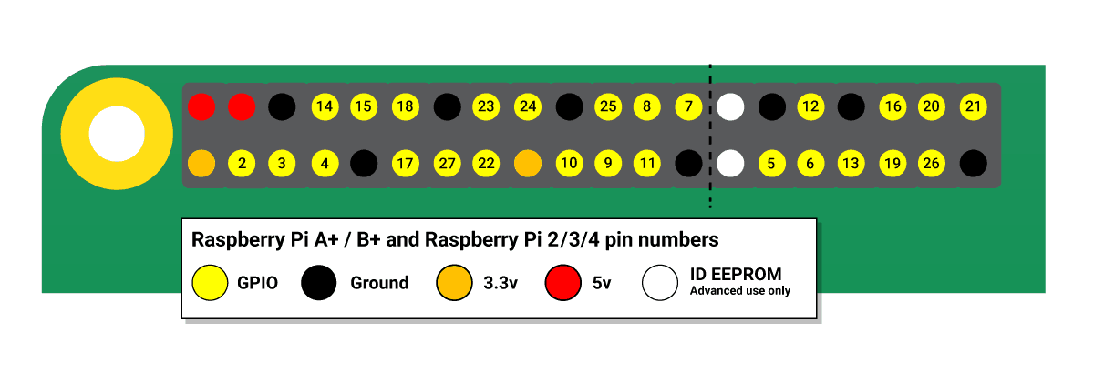
Image source:
Great, hope that clears everything up. Thanks for reading.
No, just kidding. We have more to talk about, of course. Like what “GPIO 12 (PWM1)” means, for example, or why we need all of these grounds. Remember this supposed to the best GPIO tutorial!
Power pins
Don’t worry, it doesn’t get too weird. We can start with the power pins, which include “3V3 power” and “5V power” pins. As those names suggest, these pins transmit power. Astute observers will notice that we already supply our
It’s important to know that the pins labeled “5V” and “3V3” aren’t the only pins that can supply power. As we’ll soon see, we can command other pins to send some juice as output. These are just the pins that send out power by default. If you set up an LED circuit using a 3V3 pin, you’ll find that your LED lights up whenever the Pi is on, without you needing to program anything (in fact, you don’t even need to have a micro SD in your
Grounds
And if we’re going to be rigging up electrical circuits here, we’ll need a ground. You’ll find grounds among the pins, too, of course — two types of pins down!
Standard GPIO pins
Take out the power and ground pins, and you’ll be left with the pins that are dedicated to sending output and receiving input. All of these can be used for straightforward input/output tasks, but they’re not all exactly the same. Some have the power to work with communications interfaces that others can’t handle, and some can send or receive power, too.
“Standard” GPIO pins are the most common ones on your board, and they’re capable of sending or receiving 3.3 volts. We’re going to make use of these pins in our DIY project in the second part of this
Special pin powers
Some of the “regular” GPIO pins (the ones that aren’t power or ground pins) have special talents. We won’t deal much with these in basic DIY projects, but they may be good to know for more advanced uses.
- SPI pins – SPI means serial peripheral interface, which is a communications interface best used with embedded system. In practice, this means that DIYers will use these pins to do things like connect touchscreen devices to their
Raspberry Pi . The trick, though, is that you have to use all of them at once — meaning that devices that use SPI pins dominate your whole GPIO apparatus. - UART pins – UART stands for universal asynchronous receiver-transmitter, which is a physical circuit designed to send and recieve data. This is something that most DIYers won’t be messing around with.
- PWM pins – PWM means “pulse width modification,” which is a communication protocol best used with stuff that moves and lights up: motors, LEDs, and so on.
- I2C pins – I2c is short for inter-integrated circuit (that’s two “inters”). It works similarly to SPI, but it doesn’t force you to use nearly so many pins.
Programming GPIO pins
By now, we’ve figured out that GPIO pins can communicate inputs and outputs to and from a circuit board, and we’ve seen that the various sorts of inputs and outputs we have at our disposal are not all that specific: We can use them in different ways by telling our
As you might imagine, the best way to do that is with a programming language. If you want to use the
- Scratch – Scratch is a visual programming language aimed at children. It’s primarily used for learning, though, and it’s not our best option for DIY stuff.
- C/C++ – You can use GPIO inputs and outputs in C and C++ programming with either the standard kernel interface or the third-party library pigio.
- Processing – Like Scratch, Processing is language designed to educate non-programmers.
- Python – Here’s our superstar. The highly readable Python programming language is our best bet for using GPIO pins in our code, and it’s what we’ll use in the simple DIY project that we’ll work through in the next section.
Naming the pins
If we’re going to program with GPIO pins, we need a way to identify which pins we’re talking about. We’ll have options here, because every pin has two names. First, there’s the BOARD name, which refers to a given pin’s position on the
Now that we know what GPIO pins are, how they work, and a little bit about how we might program them, we can do a simple DIY project to apply our new knowledge.
A simple Raspberry Pi GPIO tutorial project
It’s one thing to understand that GPIO pins can be used in code and DIY projects, and another thing to actually pull it off. To get ourselves acclimated, we’re going to start with this very straightforward GPIO pin tutorial project. We’re just going to control an LED on a broadboard with our
When we’re all done with this, we’ll have our
Parts list for this project
If you’d like to build this project yourself, here’s a handy parts list to get you started:
- Raspberry Pi with 40 GPIO pins (RPi 3, RPi 4)
- Raspberry Pi power supply
- Compatible HDMI cable (and a monitor or TV to connect it to)
- micro SD card with Raspbian disk image installed
- Broadboard
- Breadboard wires
- 330 ohm resistor
- LED
Got everything? Then let’s get started. First, we’ll set up our circuit.
Step 1: Turn off your Raspberry Pi
You don’t want to short anything out here, so let’s switch off that Pi, shall we? While it would be tough to hurt yourself with the kinds of charges we’re dealing with here, it’s all too easy to hurt your Pi. Switch that bad boy off to keep it safe.
Step 2: Set up your breakout kit
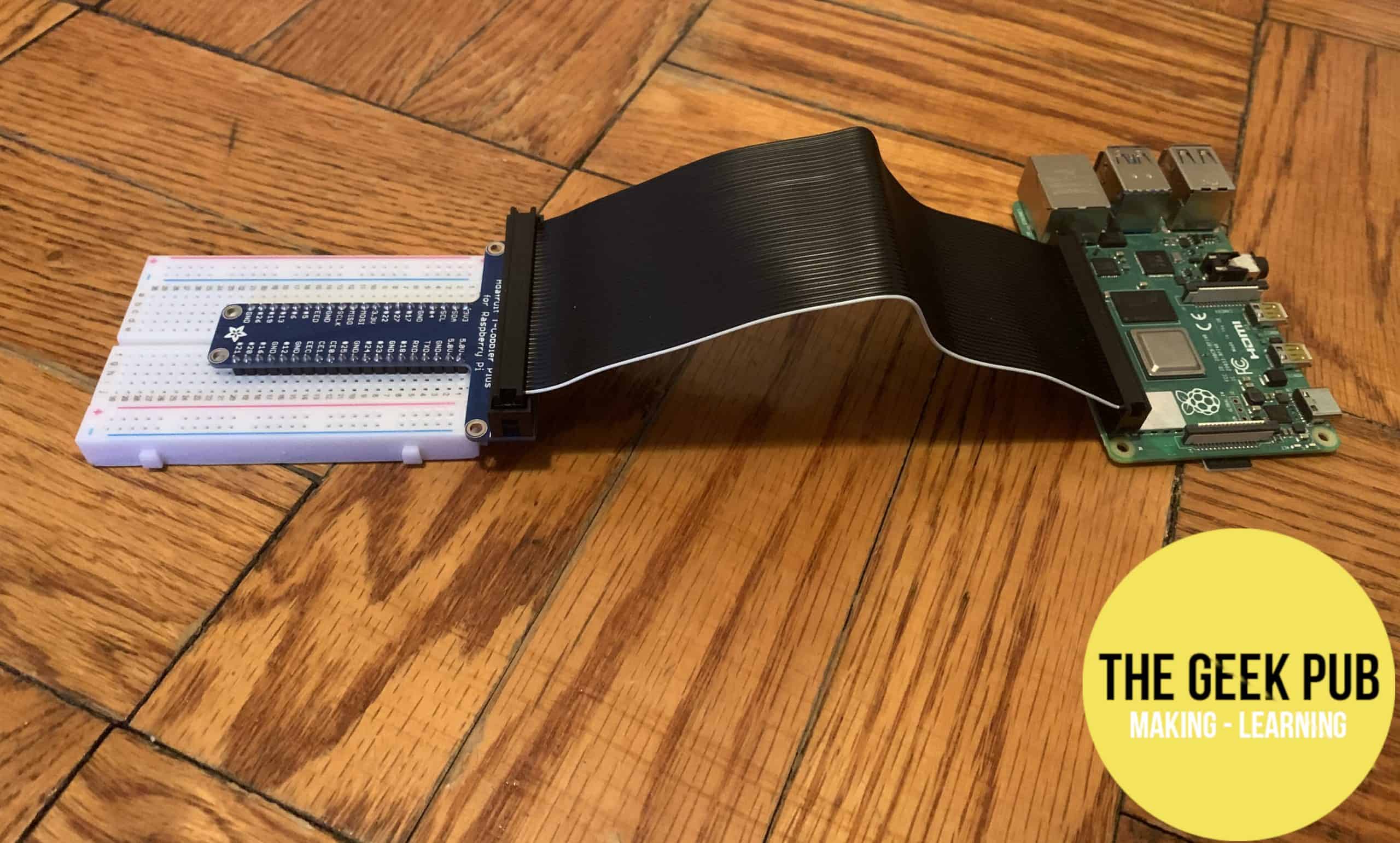
A breakout kit
While not technically required, this will make things much easier for you and a bit safer for your
A brief mention of how breadboards work is important here. The holes in breadboards are connected to other holes by pieces of metal that run underneath the plastic bits. The holes with red and blue lines running along them are called the “rails,” and they’re connected parallel in the directions those lines run (but never across — the red and blue are two separate rails that run separate and parallel. The rows of holes closer to the center of the board are called “columns,” and they’re connected in rows — that is, perpendicular to the direction that the rails are running. The rails and columns are not connected, and the columns are not connected to the columns next to them. Nor are they connected to their counterparts across the little gap in the middle of the board (which is called the “valley”).
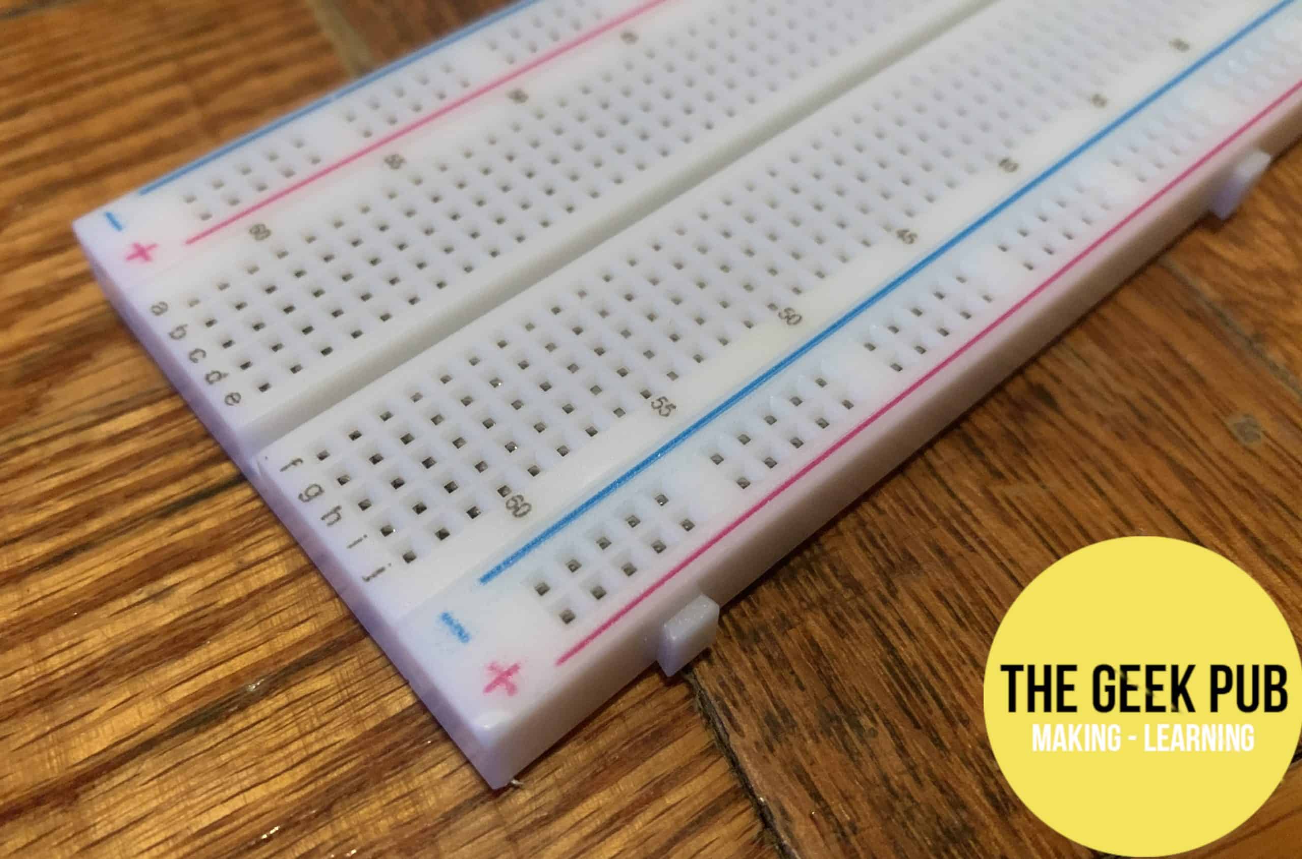
A breadboard
If you’re using a breakout kit, you’ll want to stick your breakout pins in such that they each get their own column. That means that the valley should run between the two sets of pins on your breakout set. Oh, and don’t forget to snap that bad boy in there (carefully, though) — it should go all the way into the breadboard.
Step 3: Connect a ground GPIO pin to the breadboard rail
If you’re familiar with breadboards, you’ll know that the “rail” is the line of holes marked in blue. The holes in the rail are all connected by a piece of metal that runs underneath them in the breadboard. Stick a breadboard wire into a hole on that rail.
Now take the other end of the wire and connect it to a ground pin on your
Step 4: Use a resistor to connect the rail and any column on the breadboard
As you’ve probably noticed, we’re working backwards towards the power GPIO pin. That means our next stop is the resistor.
Stick the wire on one end of the resistor into the same rail that you used in Step 3. Then stick the other end in any column you want. The columns are the little rows of holes in the middle of the breadboard — in other words, the holes that aren’t on the rails. Any of those holes will do.
By the way, your resistor may be a pretty leggy boy. Feel free to trim the wires on each end a bit if you care about the aesthetics here.
Step 5: Connect the LED between the column with the resistor and a new column
Our next stop on our circuit is the star of the show: The LED. It matters which end of the LED wire you stick where on this step, so be careful.
One of the two wires sticking out of your LED should be longer than the other. It may also have a bend in it. That’s the one that we want to receive the
So go ahead and insert your LED with the shorter wire going into the rail with the resistor and the longer wire going into a new, unused column.
Step 6: Connect the LED’s column to a standard GPIO pin
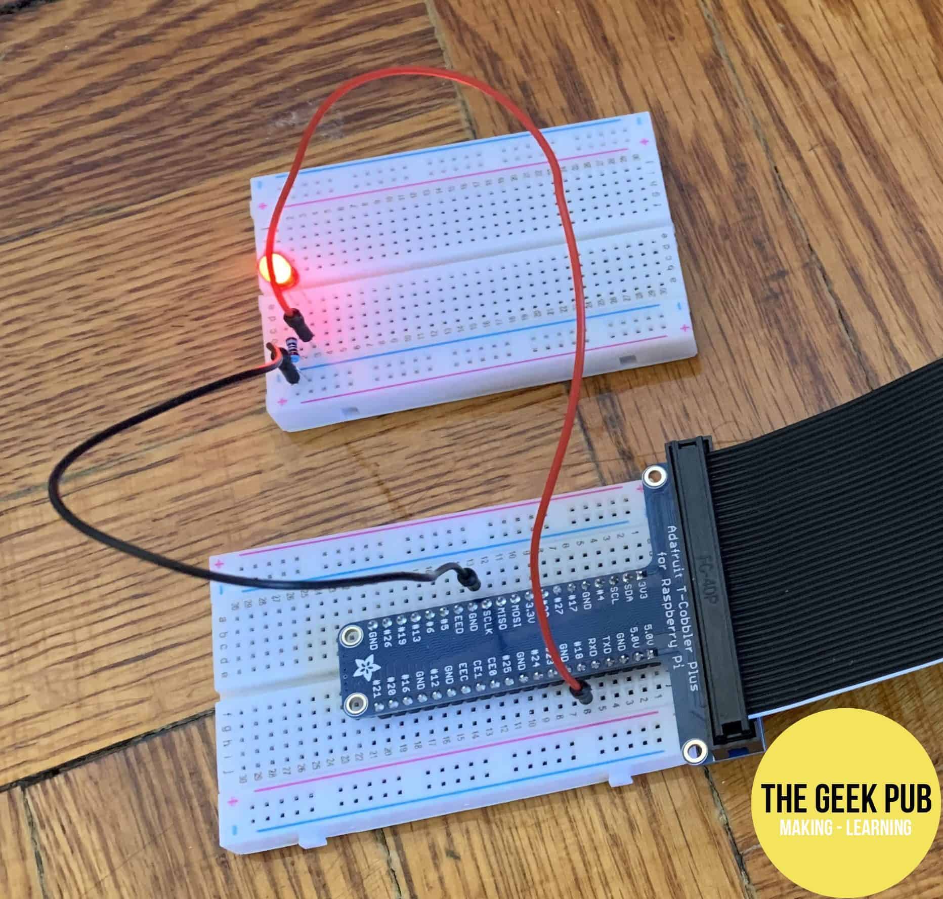
The finished circuit in action. Note that the LED should be turned off on yours until you run the program.
We’re just about done here. All we have to do now is connect the LED to a GPIO pin that can provide it with 3.3 volts when we tell it to. A standard GPIO pin will work just fine for that, which means we can choose between 7, 11, 12, 13, 15, 16, 18, 22, 29, 31, 32, 33, 35, 36, 37, 38, and 40. Let’s agree to use the same one so that we can use the same code later on, okay? We’ll use pin 18.
Stick one end of a breadboard wire into a hole on the same column that you stuck the long LED wire into — that is, the one without the resistor.
Then connect the other end of that wire to pin 18 on your
Step 7: Coding time!
We now have a simple circuit set up that runs from a potential power source (our
And since we’re using GPIO pins, we have all kinds of control over if and when we’re powering up this circuit. We can write a little program that will light up this LED however we want — we could make it flash out Morse code, turn off and on to the beat of “Another One Bites the Dust,” or whatever else we dream up. For now, though, we’ll keep things simple. We’ll write a program that will turn on the LED, wait five seconds, and then turn it off again.
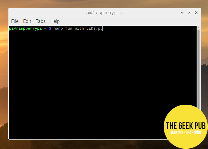
Let’s open nano!
So turn on your
Or, you know, whatever you want to call it.
Step 8: Writing the code and lighting the LED
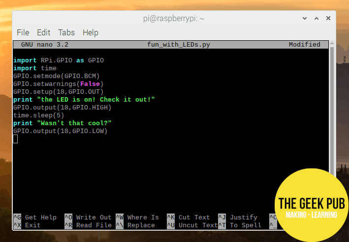
The finished code as seen in nano
In the next step, we’ll break down our code to figure out how it’s working. But let’s have dessert before dinner and light up our LED first. Here’s what your finished code, which is written in Python, should look like. Note that the number 18 refers to the GPIO pin that we used back in Step 6 — if you used a different one, you should replace the code’s three references to 18 with the relevant number.
import RPi.GPIO as GPIO
import time
GPIO.setmode(GPIO.BCM)
GPIO.setwarnings(False)
GPIO.setup(18,GPIO.OUT)
print “The LED is on! Check it out!”
GPIO.output(18,GPIO.HIGH)
time.sleep(5)
print “Wasn’t that cool?”
GPIO.output(18,GPIO.LOW)
Save this file and you should be able to run the script by entering the command sudo python fun_with_LEDs.py (or, you know, whatever you called it) in Terminal on your
Step 9: Breaking down our code: How did this work?
This is our best effort at a GPIO tutorial, but there’s really nothing too crazy going on with the GPIO pins themselves. The real subjects of a GPIO tutorial are wiring up breadboards (check) and writing code that makes use of the GPIO pins. In most cases, that means we’re learning Python.
Python is super simple, so explaining the code above is pretty easy. Let’s go line by line.
- import RPi.GPIO as GPIO – Our code is read by a Python “interpreter,” which is, as the name suggests, a program that knows how to read Python. But our
Raspberry Pi ‘s specific GPIO pin layout is not the sort of thing that would be important to include in a universal programming language or its interpreter. If we just start telling it to fire up pins, it won’t know what we’re talking about. That’s why we use this line to import a “library,” which is basically just an expansion pack of Python goodies. Now we’ll be able to use commands that we couldn’t before. - import time – Another library! This time, we’re importing the time library. This will let us use the
Raspberry Pi ‘s internal clock in our code. - GPIO.setmode(GPIO.BCM) – This looks like one of the weirder lines, but it’s pretty simple. There are two naming conventions for GPIO pins that Python (with our added GPIO library) will understand. We talked about this up above in the Programming GPIO pins section, which came right before this step-by-step DIY project section.
- GPIO.setwarnings(False) – Python might have some GPIO warning messages for us, but we live dangerously and don’t care about those, right? Right. This makes sure that they aren’t printed to the screen while we’re enjoying our beautiful program.
- GPIO.setup(18,GPIO.OUT) – We’re setting things up here! GPIO.setup takes two arguments: a pin number and what we’re using it for. The number here should correspond to the GPIO pin we’re using, and we want GPIO.OUT because we want output, not input.
- print “The LED is on! Check it out!” – This prints a message to our screen. The message is not true yet, strictly speaking, but it will be true almost instantly.
- GPIO.output(18,GPIO.HIGH) – We’re outputting something over the GPIO pins. GPIO.output takes two arguments. The first is a pin number. We can put our buddy in there because we set him up for output a couple of lines of code ago. The second is the output, which in this case is GPIO.HIGH. A HIGH output for a standard GPIO pin is 3.3 volts. The net result here is that our LED turns on. We are liars no more!
- time.sleep(5) – Good thing we imported that time library in the second line of our code. Now our interpreter knows how to read this time command, which tells our program to take a snooze for five seconds. As the program pauses, everything stays as it was — which means the power GPIO pin keeps outputting juice to the LED, and we can admire our handiwork.
- print “Wasn’t that cool?” – We’re printing things to the screen again. Wasn’t it cool to see the light turn off and then on again, we ask, even though the light is actually still on? Don’t worry about the little fib. The light will be off before you know it.
- GPIO.output(18,GPIO.LOW) – And just like that, the LED goes out again. This is our GPIO.output command again, taking the same arguments as last time but, this time around, going with GPIO.LOW as the output. That means 0 volts.
If that all seemed pretty simple, that’s because it was! Python is a very straightforward language that stresses readability and make liberal use of libraries. Of course, you could easily build on this project by setting up a more complicated circuit (or multiple circuits) and writing more interesting code. That’s all up to you! For the purposes of our
GPIO pins and Raspberry Pi accessories
In the project that we just ran through, we were able to set up a broad board, wires, and LEDs and connect that apparatus to our
You can probably see the implications here. The GPIO pins don’t much care if they’re attached to simple things or complex ones, and they also don’t care if they’re rigged up to DIY projects or to professionally manufactured circuits. While we here at TheGeekPub admire your individualism and self-reliance, it is all the same to the GPIO pins. So it’s no surprise that there are a ton of manufactured
There are lots of these sorts of accessories, but we’ll pick one here to use as an example here in our
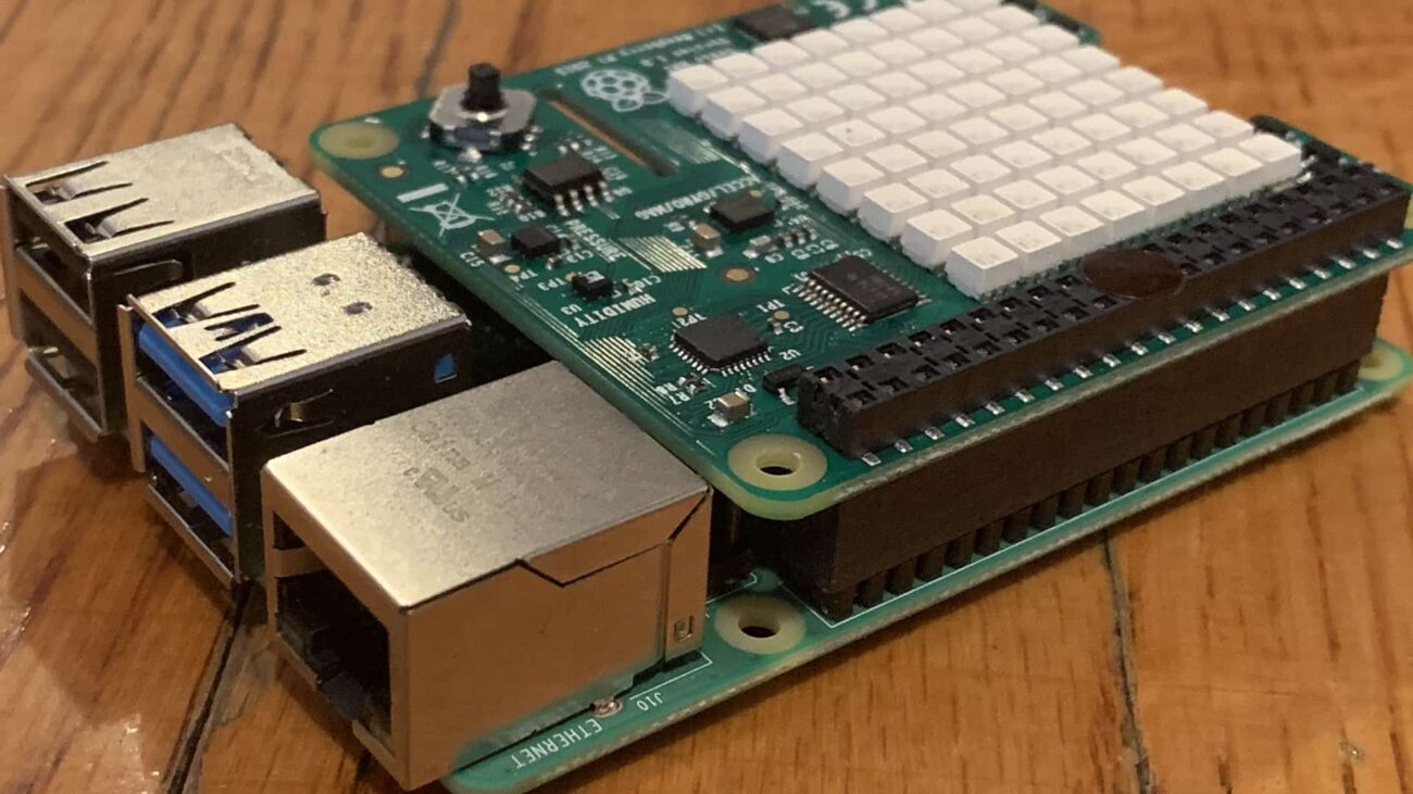
Meet the sense HAT
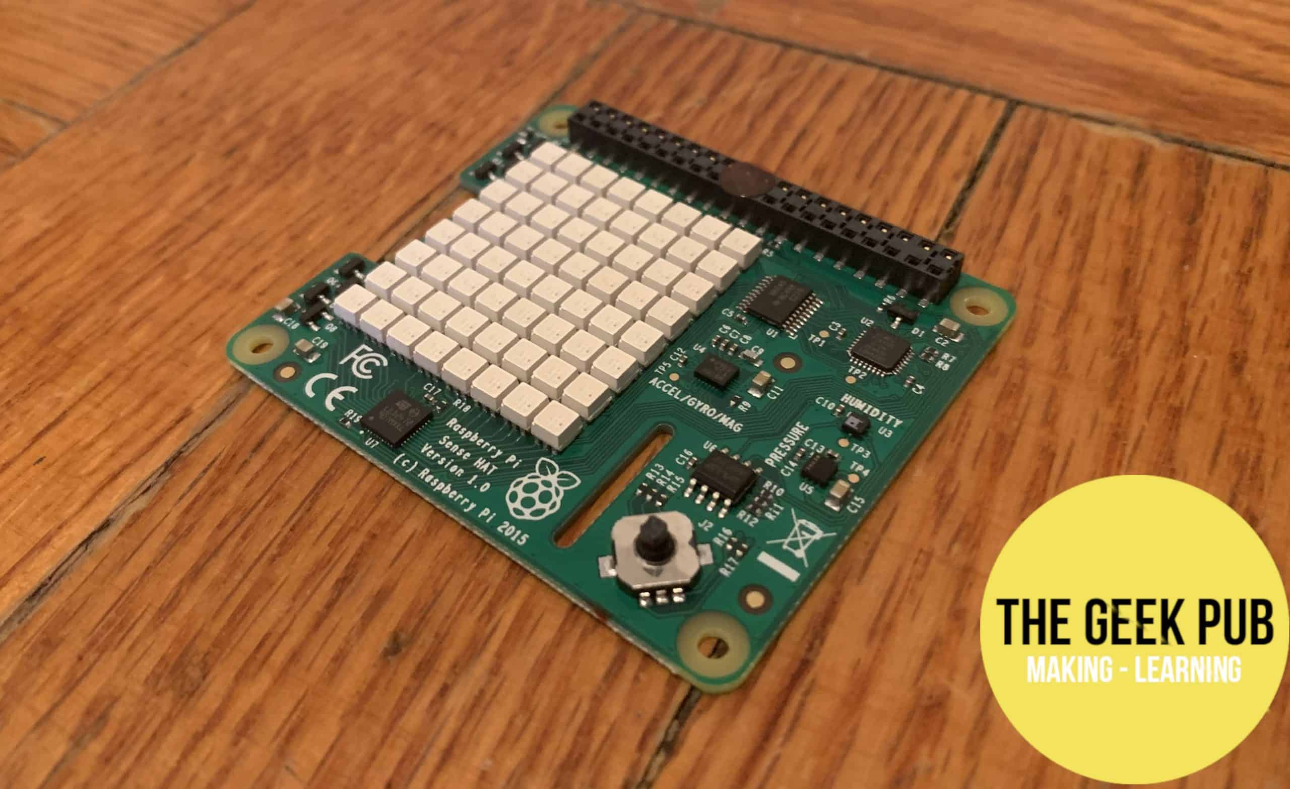
The sense HAT
The sense HAT looks like a little circuit board with some stuff attached to it — a bit like the
You don’t have to be in Space to get something out of this device, though. The sense HAT has sensors that can measure temperature, humidity, pressure, and the orientation of the board. It also boasts a matrix of LEDs.
The sense HAT communicates information using the GPIO pins — which, of course, is why we’re talking about it here. The sense HAT is designed to fit right on top of a
Grab this accessory, and you’ll have even more DIY options. You could use the LED matrix to set up a digital clock, for instance, or you could use the sensors on the sense HAT to take stock of the weather and then beam that information to your computer or another device using the
A simple Raspberry Pi sense HAT tutorial project
Earlier in this GPIO tutorial, we programmed GPIO pins for use with a broadboard circuit. Now, let’s try a project that uses a professionally manufactured accessory. We’re going to have the sense HAT measure the temperature and then print the result to our screen — a super-simple task that won’t take us long at all. Here’s what you’ll need:
Parts list for this project
If you’d like to build this project yourself, here’s a handy parts list to get you started:
Raspberry Pi with 40 GPIO pins (any model since 2014)Raspberry Pi power supply- Compatible HDMI cable (and a monitor or TV to connect it to)
- micro SD card with Raspbian disk image installed
- sense HAT
Let’s get started.
Step 1: Attach your sense HAT to your Raspberry Pi
With your
RELATED: Raspberry Pi Sense HAT Clock Project
The sense HAT is designed to sit right on top of a modern
Step 2: Install the sense HAT software
If you haven’t already done so, hop into Terminal on Raspbian and enter these commands to update Raspbian (always a good idea), install the sense HAT software, and reboot your
sudo apt-get update
sudo apt-get install sense-hat
sudo reboot
Step 3: Coding time!
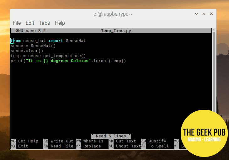
The code we’ll use for our sense HAT project
Turn on your
Here’s the code we’ll use:
from sense_hat import SenseHat
sense = SenseHat()
sense.clear()
temp = sense.get_temperature()
print(“It is {} degrees Celcius”.format(temp))
Now you can run your code with the command sudo python Temp_Time.py (or whatever you want to call it). The temperature should be printed to the screen. We’re already done!
Step 4: Understanding our code
Let’s take a closer look at the code that we just used so that we’re sure we understand it. It’s worth nothing one thing about this code that you may not have expected: It makes no mention of the GPIO pins!
Because the sense HAT has its own library, we can import a bunch of commands that tell our
Here are the details, line by line:
- from sense_hat import SenseHat – this imports the sense HAT library for Python, which makes our task here very, very easy.
- sense = SenseHat() – This is a Python thing called “object instantiation.” We’re taking the SenseHat() class (a class is a group of related things in Python) and assigning the variable “sense.” Now we can reference the sense hat class in our commands using “sense” followed by the dot operator (just a period: “.”) and then the command we want.
- sense.clear() – This command just clears out old junk that might have been displayed on our sense HAT’s LED matrix. We know we’re talking about the sense HAT because we use the sense variable that we just defined.
- temp = sense.get_temperature() – as you can probably guess, sense.get_temperature() is a command that gets the current temperature from the sense HAT. The “temp =” part defines a variable. The “sense.” part indicates that we’re working with the sense HAT and its library. So this line just stores the current temperature as a variable called “temp.”
- print(“It is {} degrees Celcius”.format(temp)) – this takes the value of the variable “temp,” which we just set to be the current temperature, and prints it to the screen within a text string. Python lets us use “{}” and the .format function to pull off this trick.
And that’s it. Pretty simple, right?
Going further
Writing the best GPIO tutorial we could meant using DIY projects as examples, but we have kept things really, really simple here. You might be itching to do something more — and that’s great! The


5
This was really well written! Thank you! I just have one question. How much power can the GPIO deliver?
In the naming pins section you mention ‘the GPIO Zero Python library’ , but your code in step 8 uses the RPi.GPIO library. Is one better than the other?
0.5
1.5
5
2.5