Blog
Build a RetroPie Bartop Arcade Cabinet
Making my retro Arcade Cabinet last summer was one of my all time favorite projects. It been one of my most popular videos ever, and many of you have sent me awesome pictures cabinets you built that were based on my arcade cabinet plans. One piece of feedback that I have gotten over and over is that this cabinet is too large and too complex for many of you. Some of you wanted me to cover the electronics in the plans (rather than just the woodworking portion). Well I am happy today to bring you the RetroPie Bartop Arcade Cabinet! This cabinet, as the name implies, is much smaller and can sit on top of a desk, table, or bar. The monitor is 24 inch, instead of 27 inch, reducing the width of the cabinet by a full 4 inches. The computer is a Raspberry Pi running a RetroPie which makes installing and setting up the game system incredibly simple.
Watch the RetroPie Bartop Arcade Cabinet Video
Using the Raspberry Pi for the Bartop Arcade
Some of you will undoubtedly ask why I would use a Raspberry Pi instead of a full PC, like in my original full-size arcade build. There’s a bunch of reasons!
- The Raspberry Pi is only $35. Literally anyone can afford to buy a Raspberry Pi!
- The emulation software is pre-built and pre-configured. All you have to do is download it and place it on an SD card. It honestly couldn’t be any simpler.
- Many other games like Quake, Doom, Duke Nukem 3D and others have free ports to the Raspberry Pi which usually come included in your download of RetroPie. This means with literally no additional work, you can be playing all kinds of old PC games too.
- There are emulators for the Commodore 64, Amiga, Nintendo, Atari, etc all included.
- The RetroPie interface is clean and super easy to use.
- The Raspberry Pi has a general purpose Input/Output (GPIO) that can be used to control all sorts of things, such as flashing lights, sounds, or even flash your lighted marquee. Imagine if you get shot in Quake and the marquee flashes or the cabinet vibrates. All of that is possible with the GPIO pins of the Pi.
RELATED: RetroPie Setup Guide
All of that being said, most certainly all of this can be accomplished with a PC. It will just cost more and take a little longer and in some cases require a few extra add-on components.
The Controllers and Buttons for the Bartop Arcade
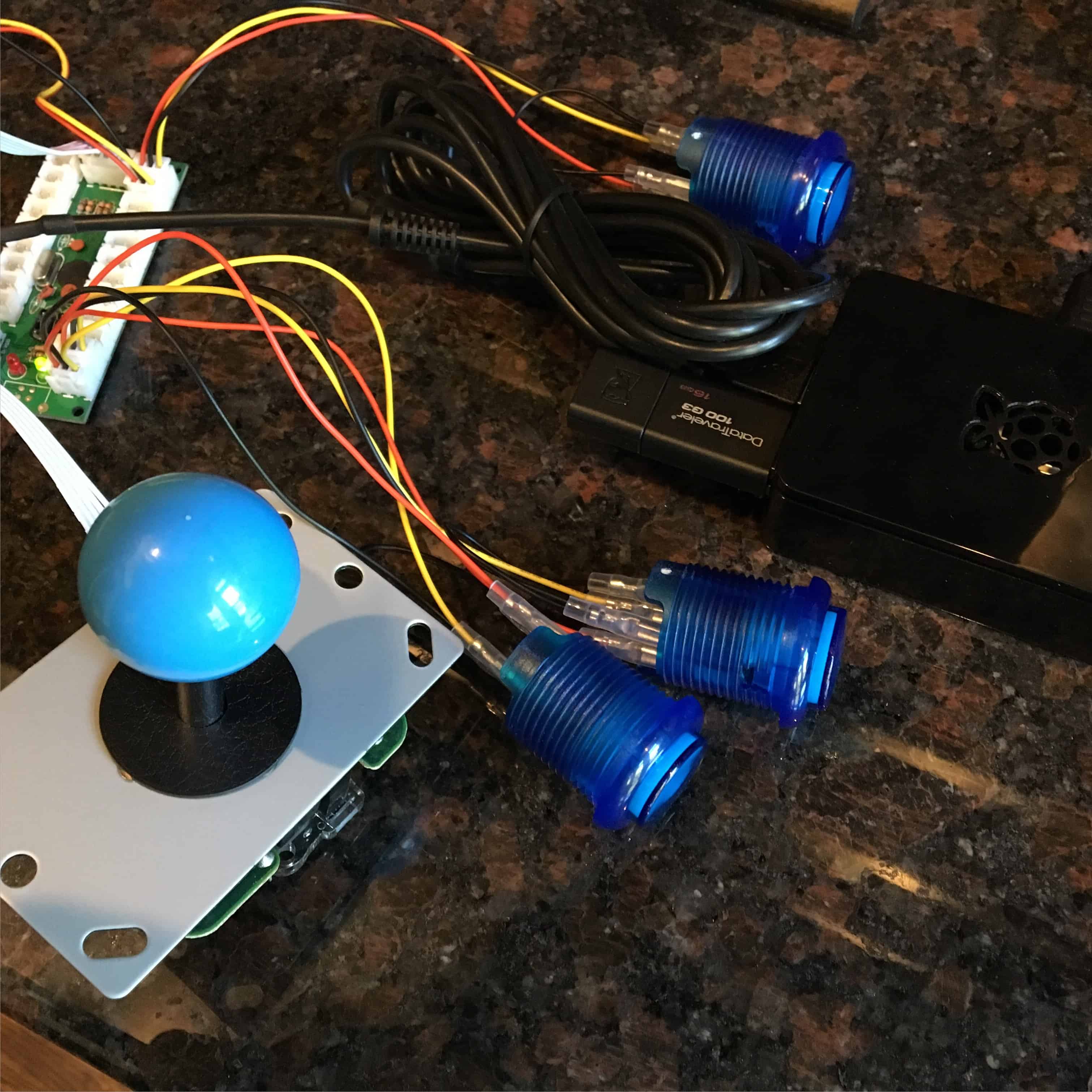
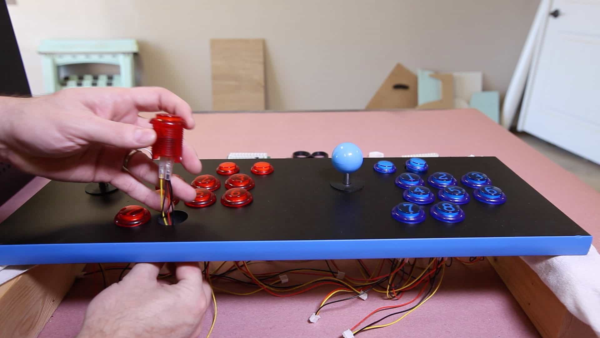
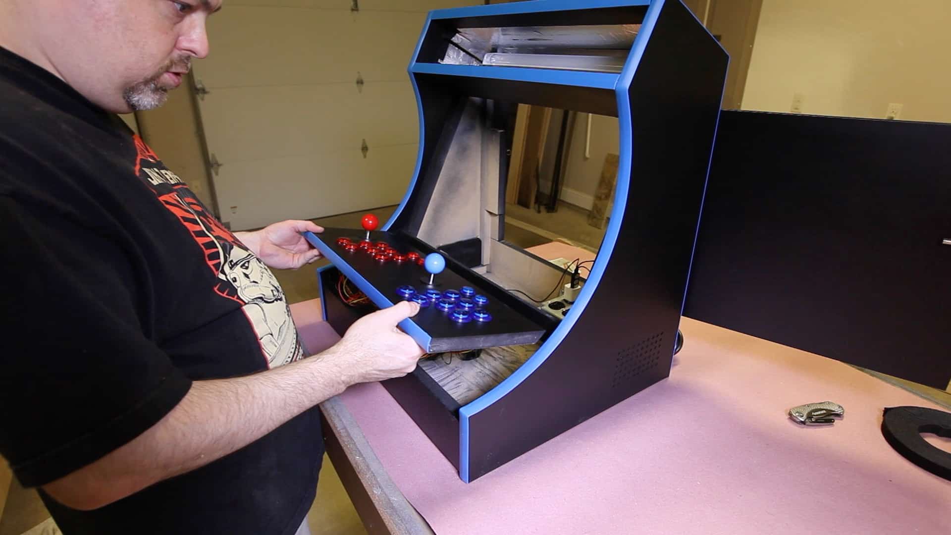
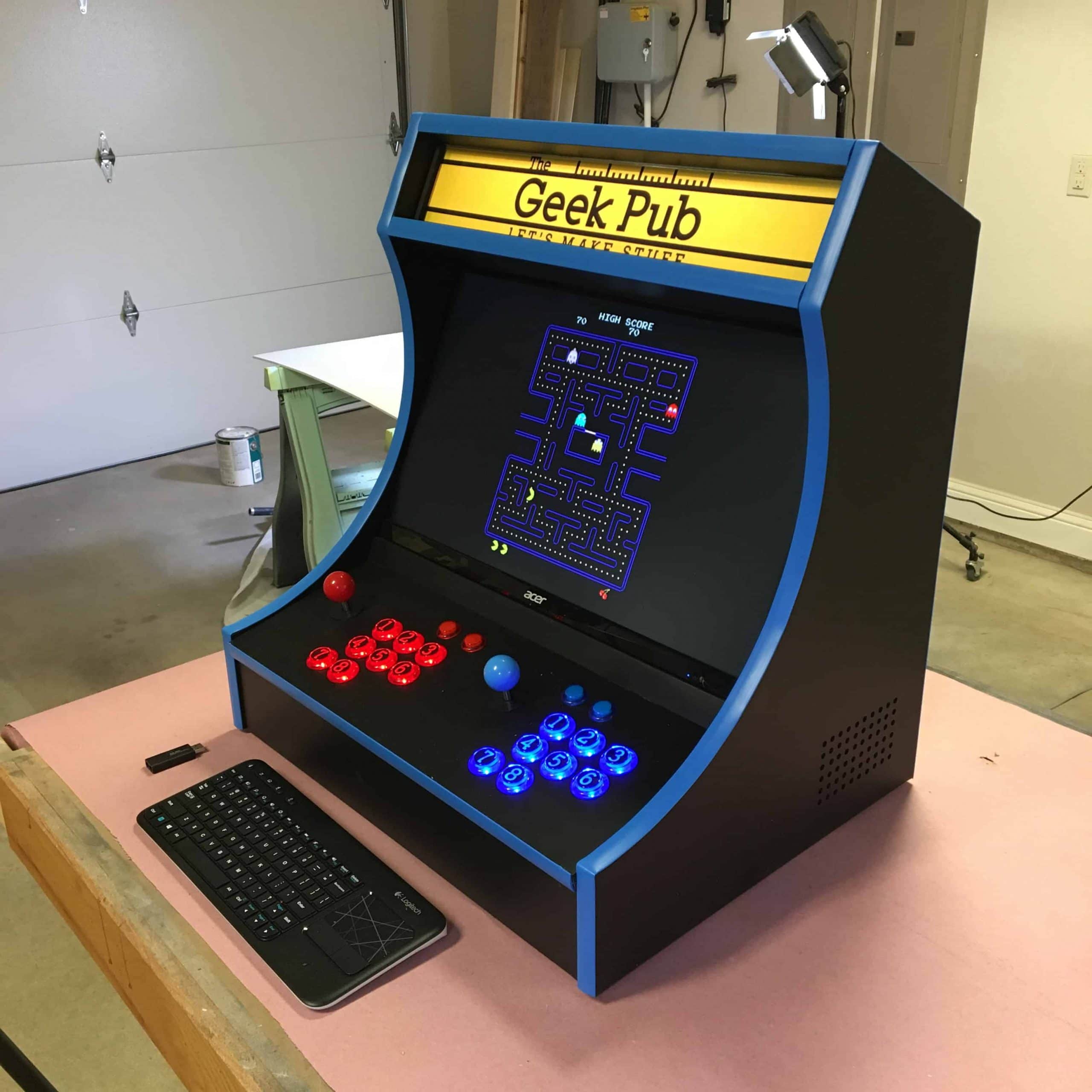
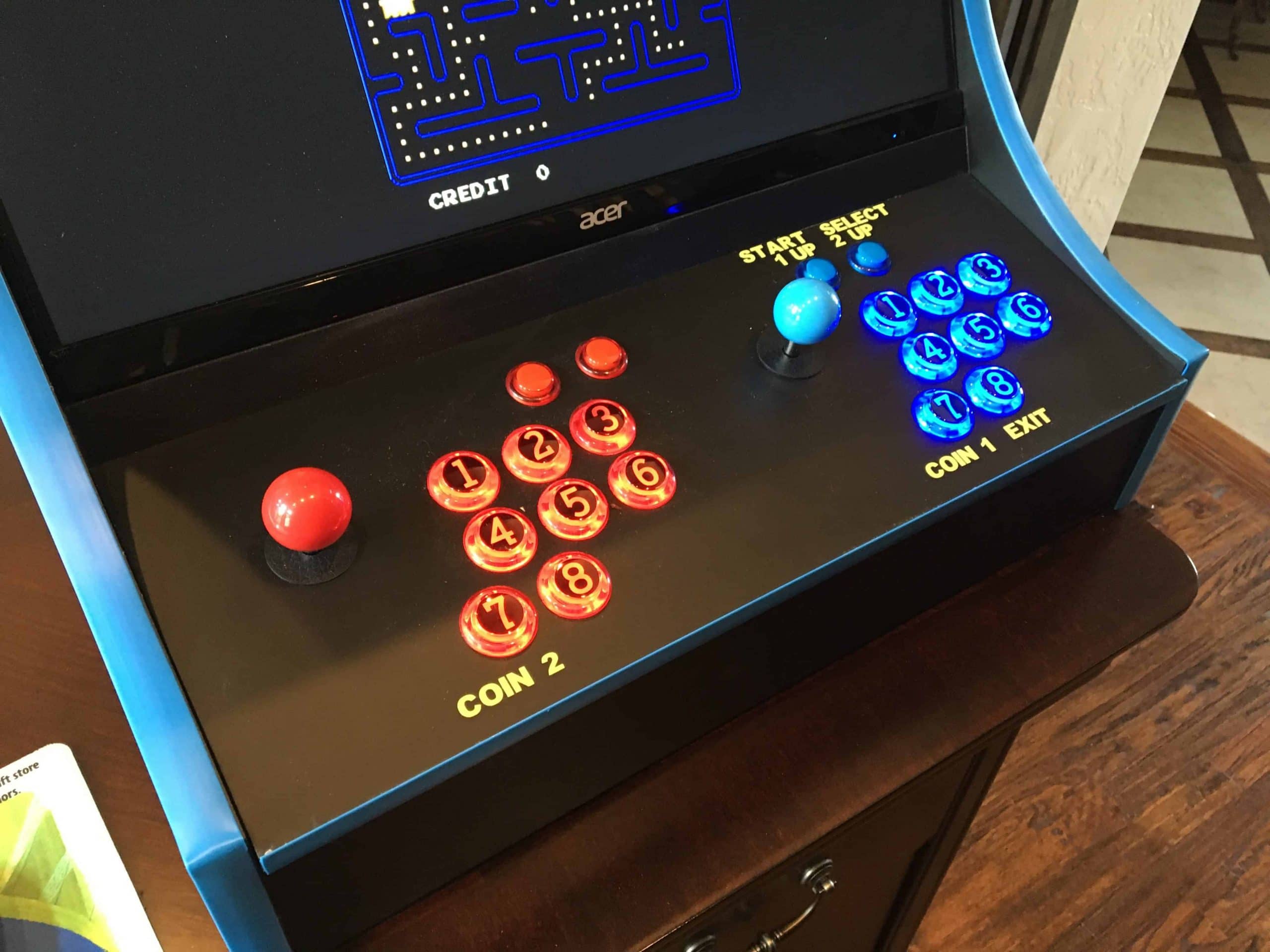
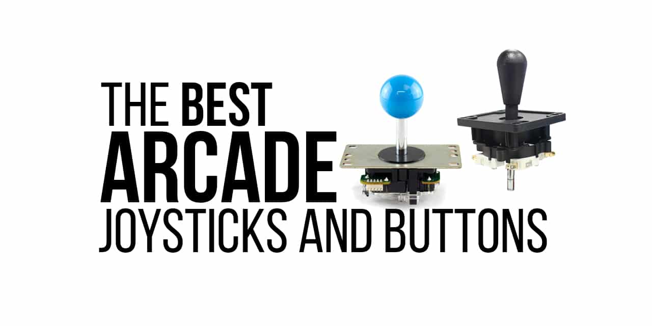
On this build I decided to switch from the X-Arcade joystick and controller over to the Sanwa Arcade Joystick & Buttons and Easyget LED Arcade Controller. I did this because I wanted to add some color to the cabinet and I also wanted the buttons to have LED lights in them, so that I could put transparent labels under the buttons. I felt like this would make a really cool effect. I bought one red joystick, ten red LED lit buttons, one blue joystick, and ten blue LED lit buttons.
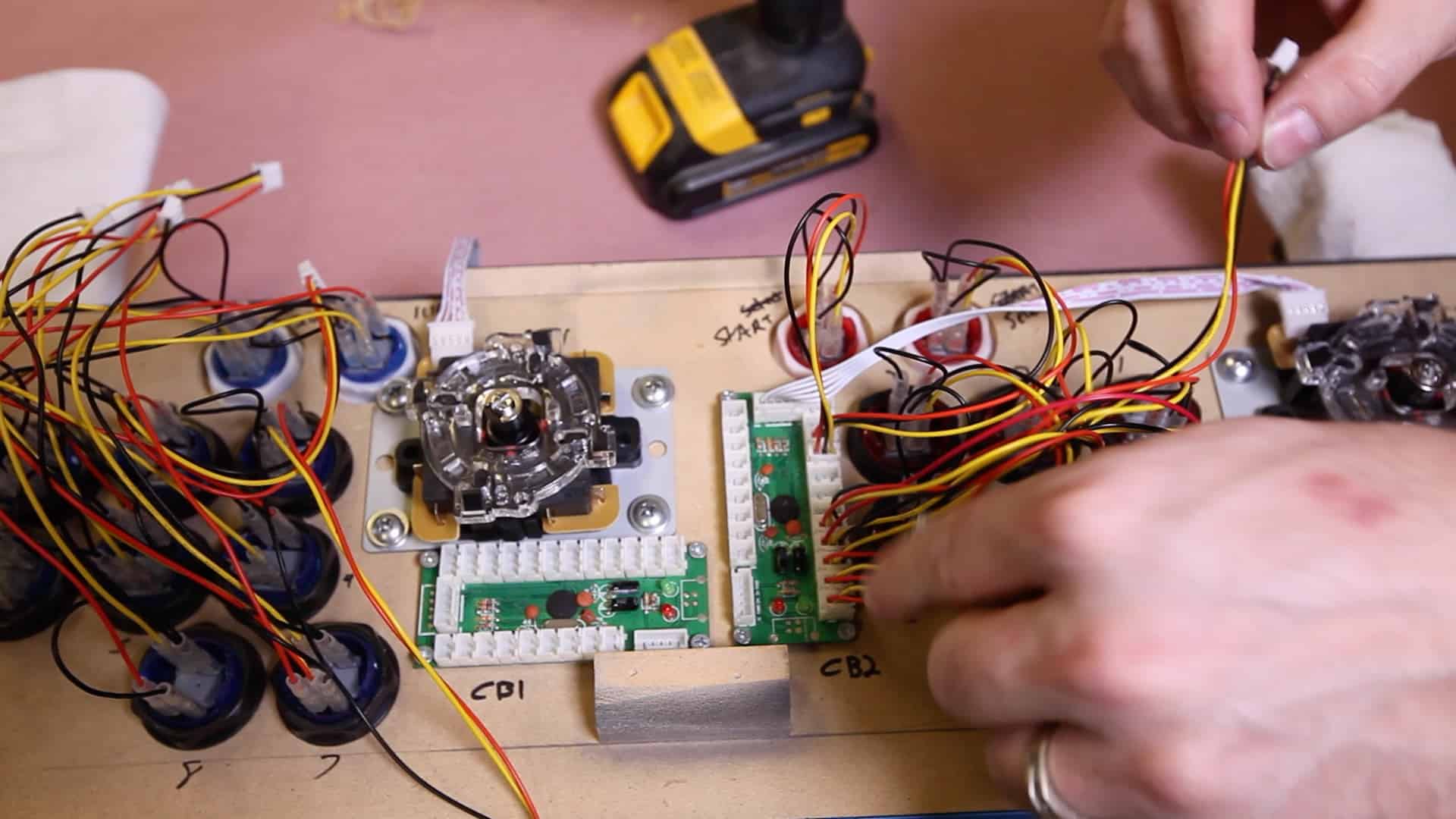
The only real downside to the Sanwa solution over X-Arcade is that each set of joystick and buttons requires a separate EasyGet controller. If USB ports are at premium in your arcade you’ll need a USB hub to use them. In addition, you’ll have to find additional space to mount each controller board on the inside of the control panel.
Finally, I do really love the ball top joystick as compared to the teardrop provided by X-Arcade. It just feels very retro and has that old-school arcade look!
Constructing the RetroPie Bartop Arcade Cabinet
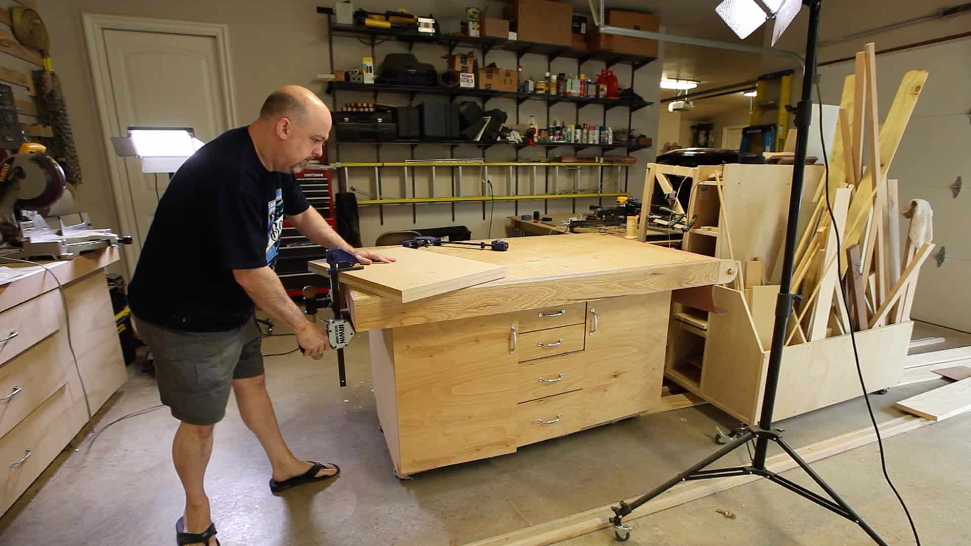
Step 1: Layout the Side Panels
The first step is to layout the side panels on a sheet of MDF. You only need to draw out one panel, because we will cut both panels at the same time.
Step 2: Draw in the Curves
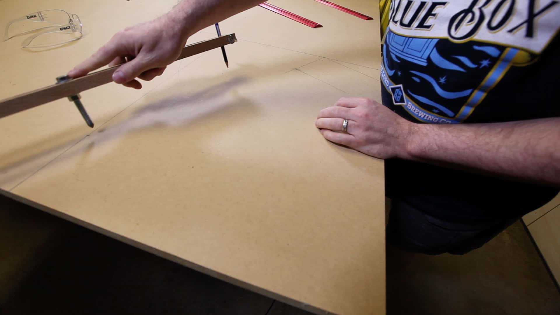
You’ll need a compass to make the curves. Unfortunately the little store bought ones won’t work. I made one out of nothing but a 14 inch piece of scrap wood and a bolt. The easiest solution would be to use a 14 inch string, with your pencil tied to one end and a nail tied to the other.
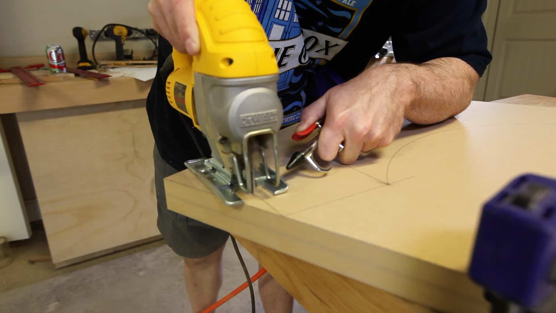
Step 3: Cut Out the Side Panels
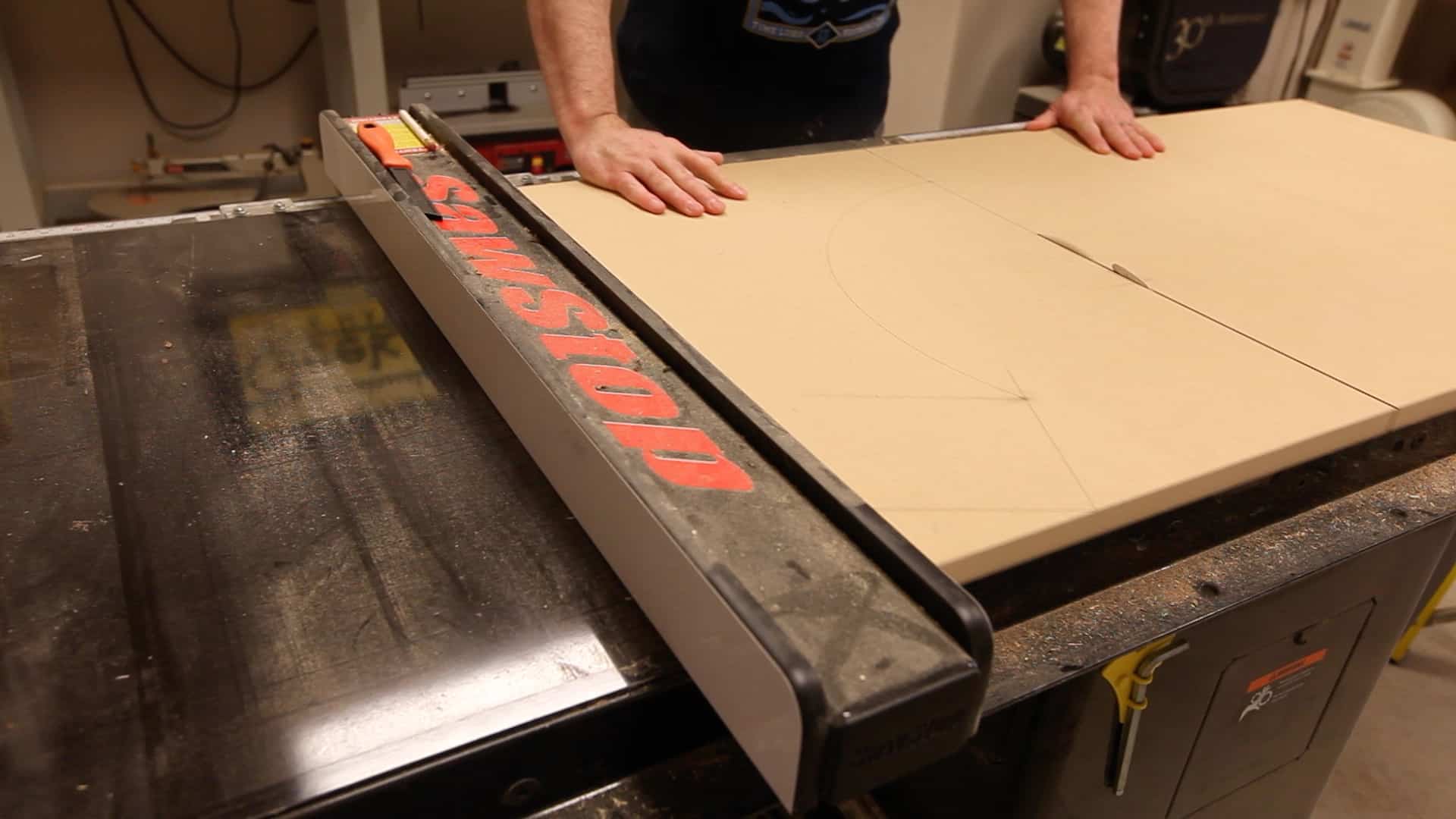
Cut the MDF panel in half and sandwich the left and right panels together. Clamp them to a table, and then use your jigsaw to cut them out. Once your finished with the cut, unclamp the sides and fold them open. This will reveal two exact copies a mirror of each other.

Step 4: Install the Connectors
To connect the side panels the center panels you could just glue and brad nail them directly together (or use screws or nails). However, that would be incredible hard to hold in place during assembly and it would also be difficult to make sure both sides were perfectly aligned and square. To make it easier, first we lay out 3/4 x 3/4 inch connectors on the panels. We can take our time and measure everything out, and then glue and brad nail those to the panels. But! This also has another great benefit: No visible nails or screws on the outside of the cabinet that will need filling later!
In my case I am using 3/4 inch MDF to build my cabinet, so these connectors are inset exactly 3/4 inch. You’ll need to adjust your spacing if you go with a thicker or thinner material.
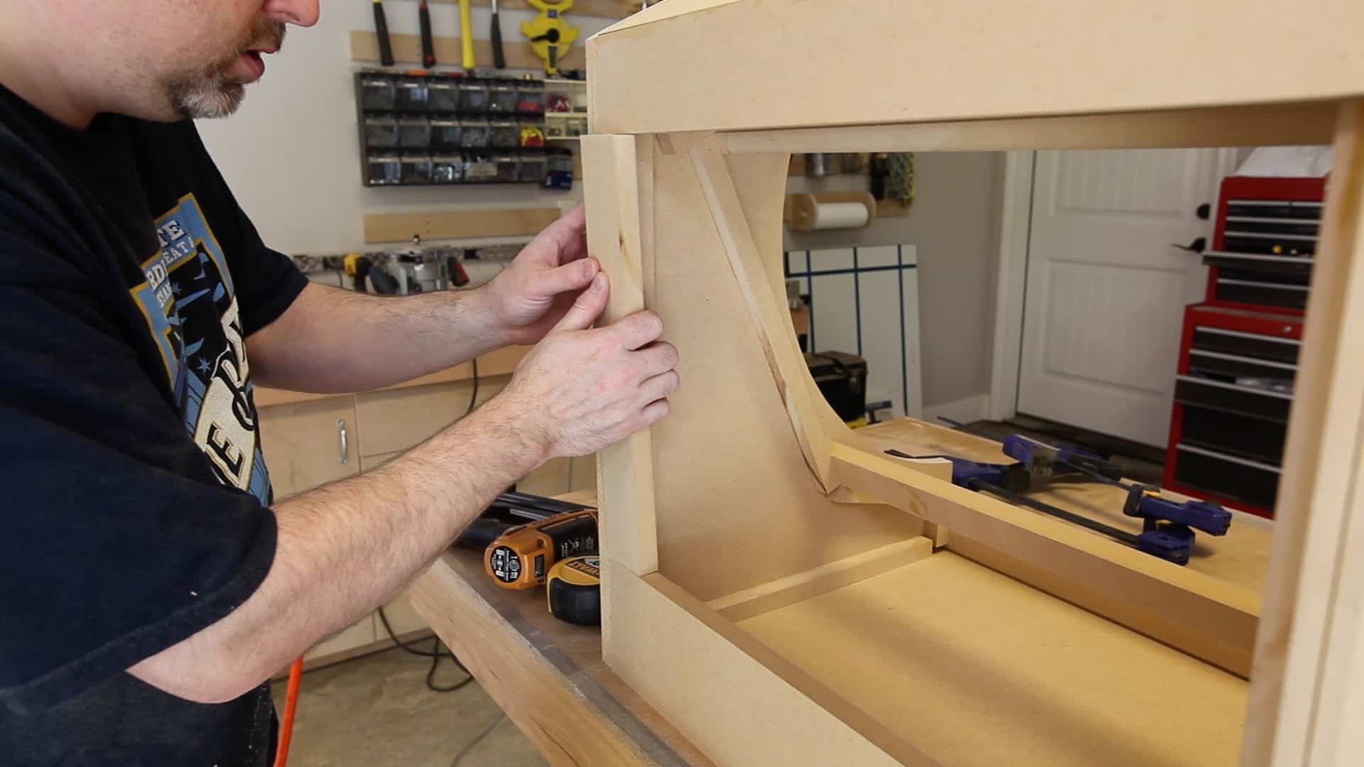
Step 5: Assemble the base Arcade Cabinet
With step 4 done, assembling the arcade cabinet is almost as easy as legos.
Step 6: Route the T-Mold Slot
This is a completely optional step depending on how you want your finished arcade to look. I personally love the retro look with T-Molding. T-Mold requires a slot in the MDF. You have to route all of the components before final assembly, otherwise your router won’t reach the internals. If you’re not going to add T-Mold, you can skip this step.
Step 7: Install the Front and Back Panels
Now that we’ve routed all of the T-Mold slots we can finish install the panels. On the backside we’re leaving a large 14 inch hole. We’ll make a door to cover this in a later step.
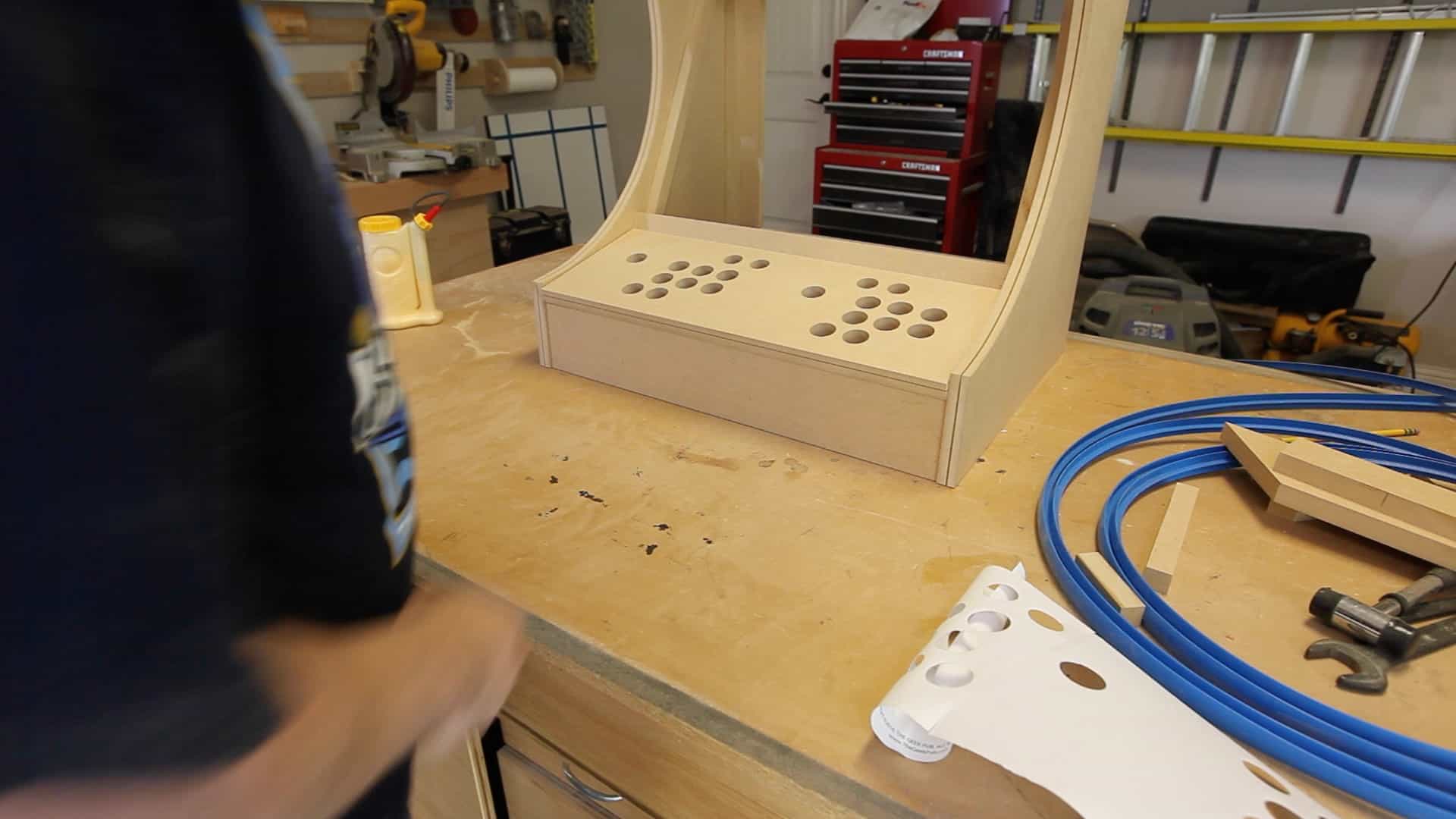
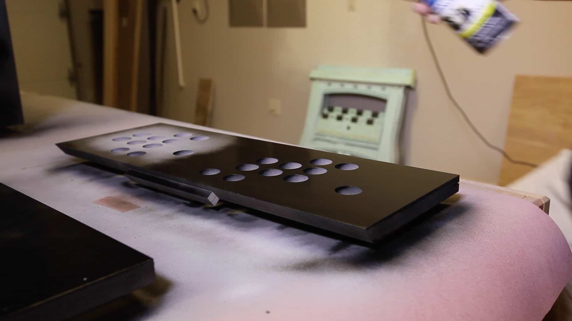
Step 8: Drill the Control Panel
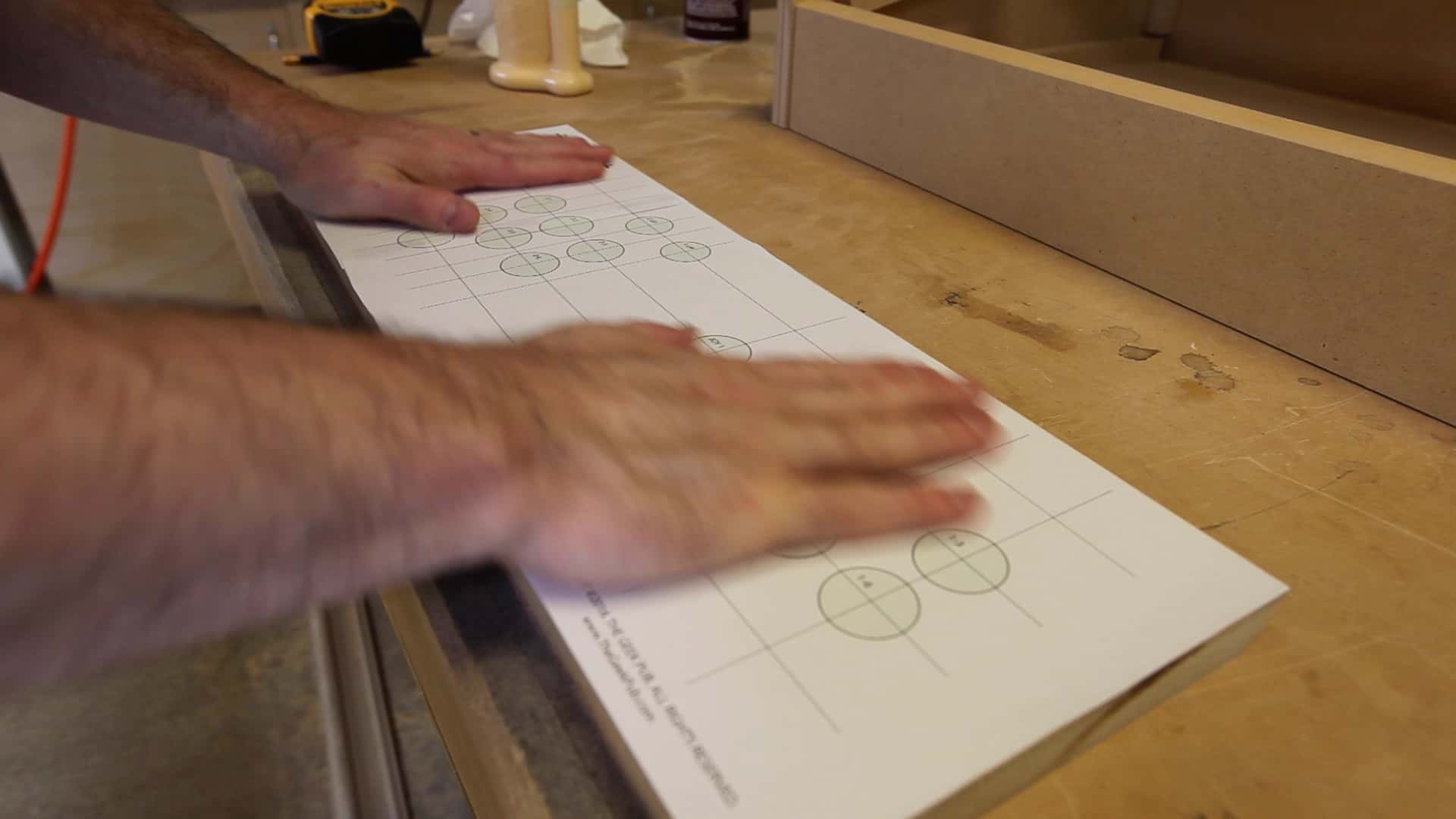
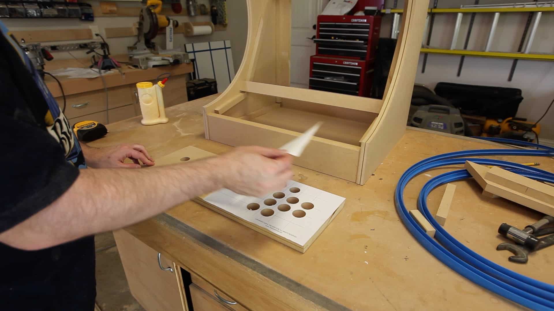
The control panel can be a real pain to drill out accurately. That’s why the plans include a glue on drilling template. Just glue this drilling guide to your control panel and with spray adhesive, drill the holes and then remove it by peeling it off. I recommend Super 77.
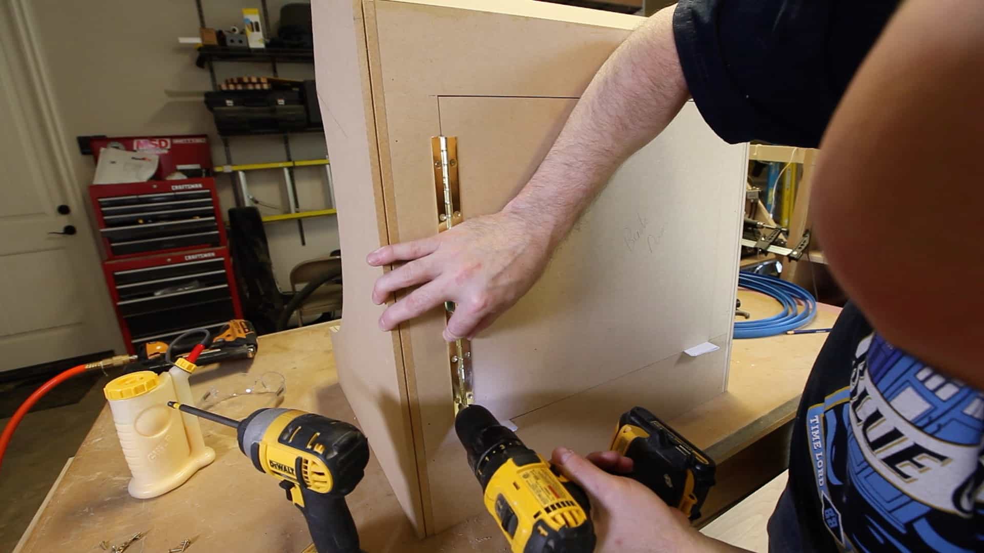
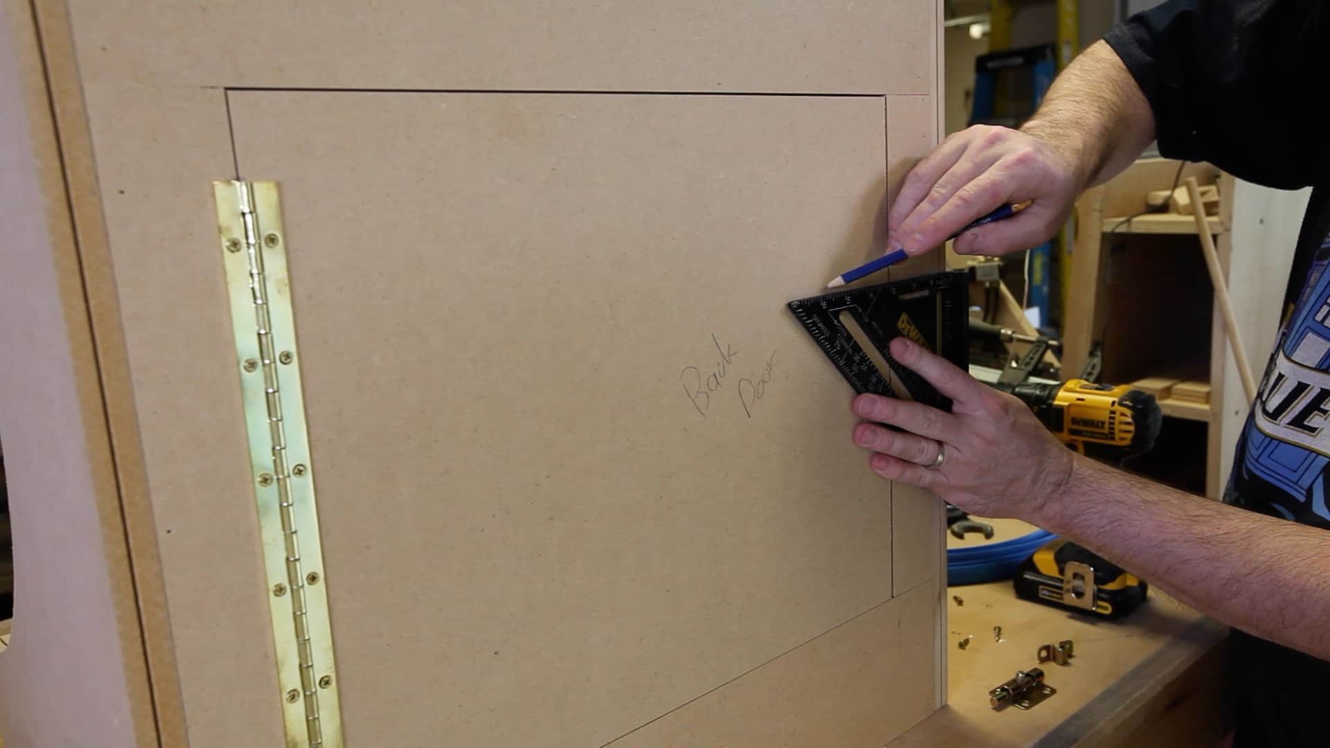
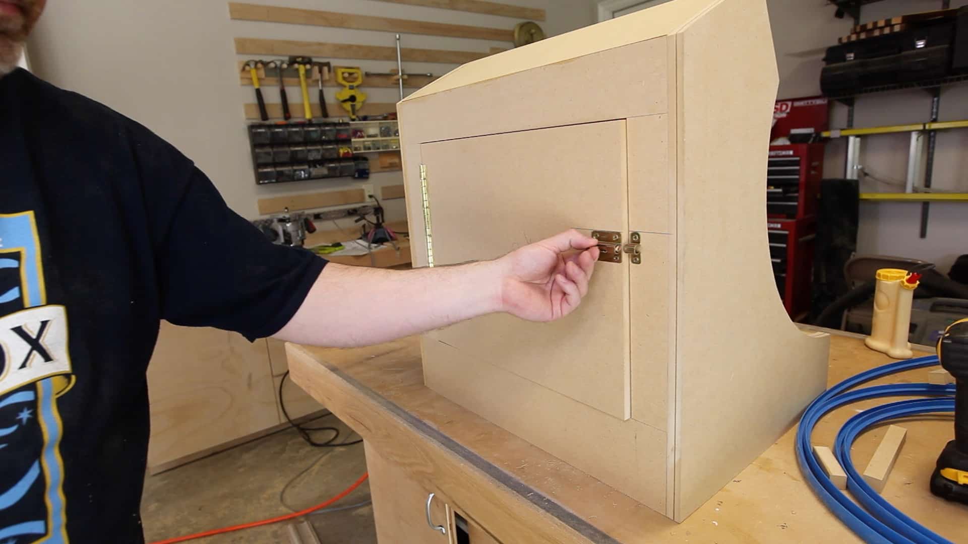
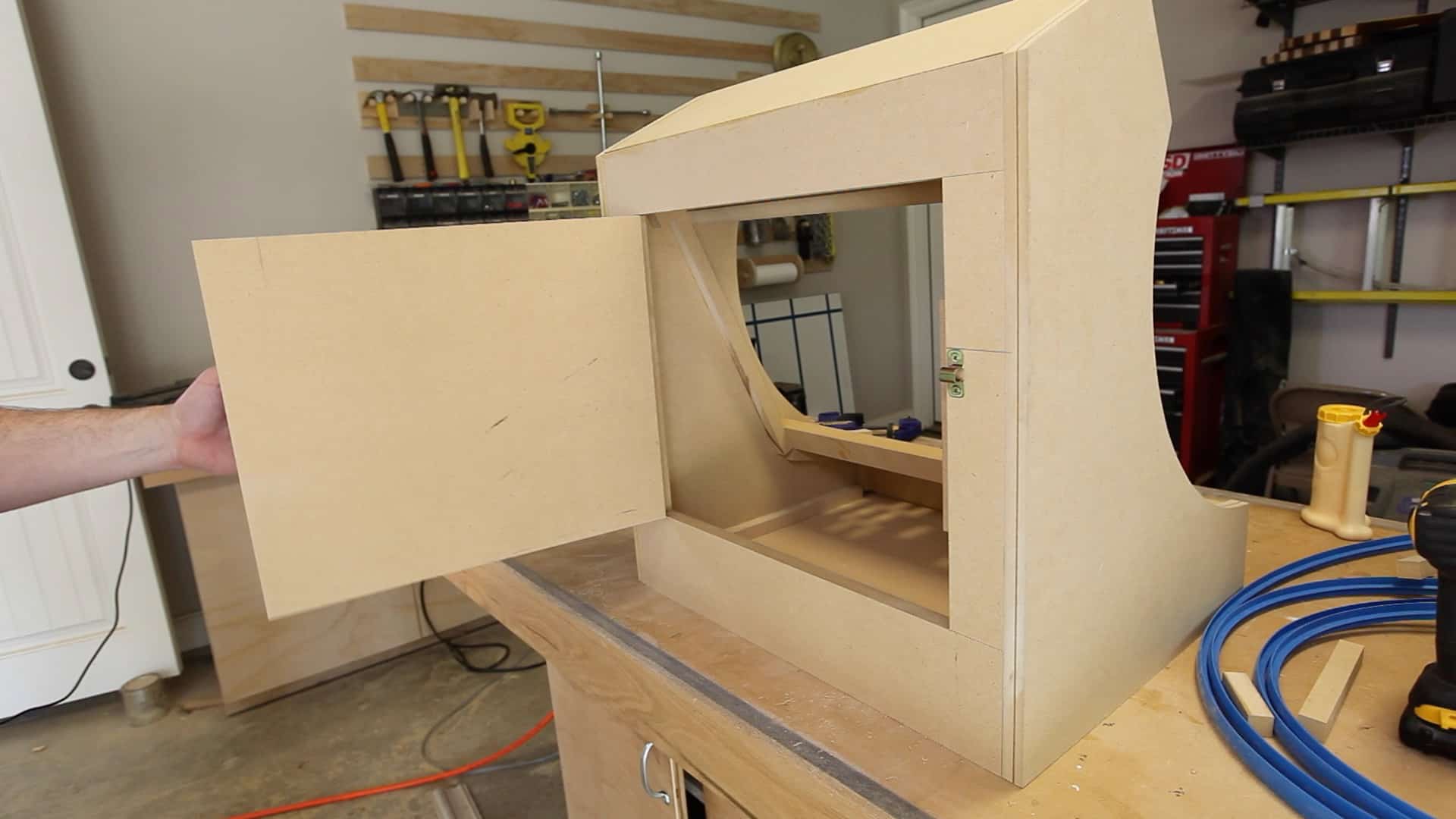
Step 9: Install the Back Door
The back door of the cabinet will be used for maintenance purposes.
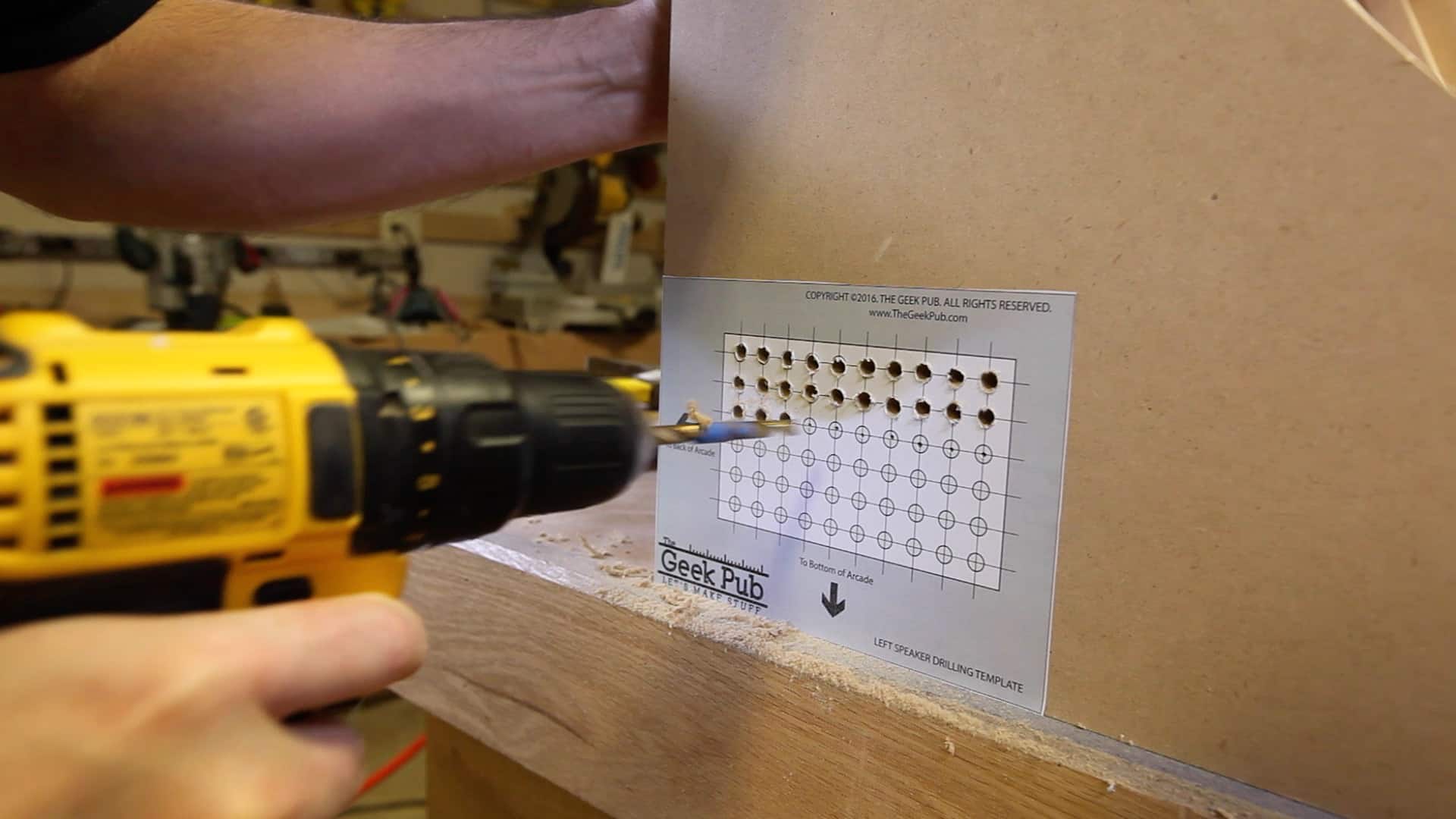
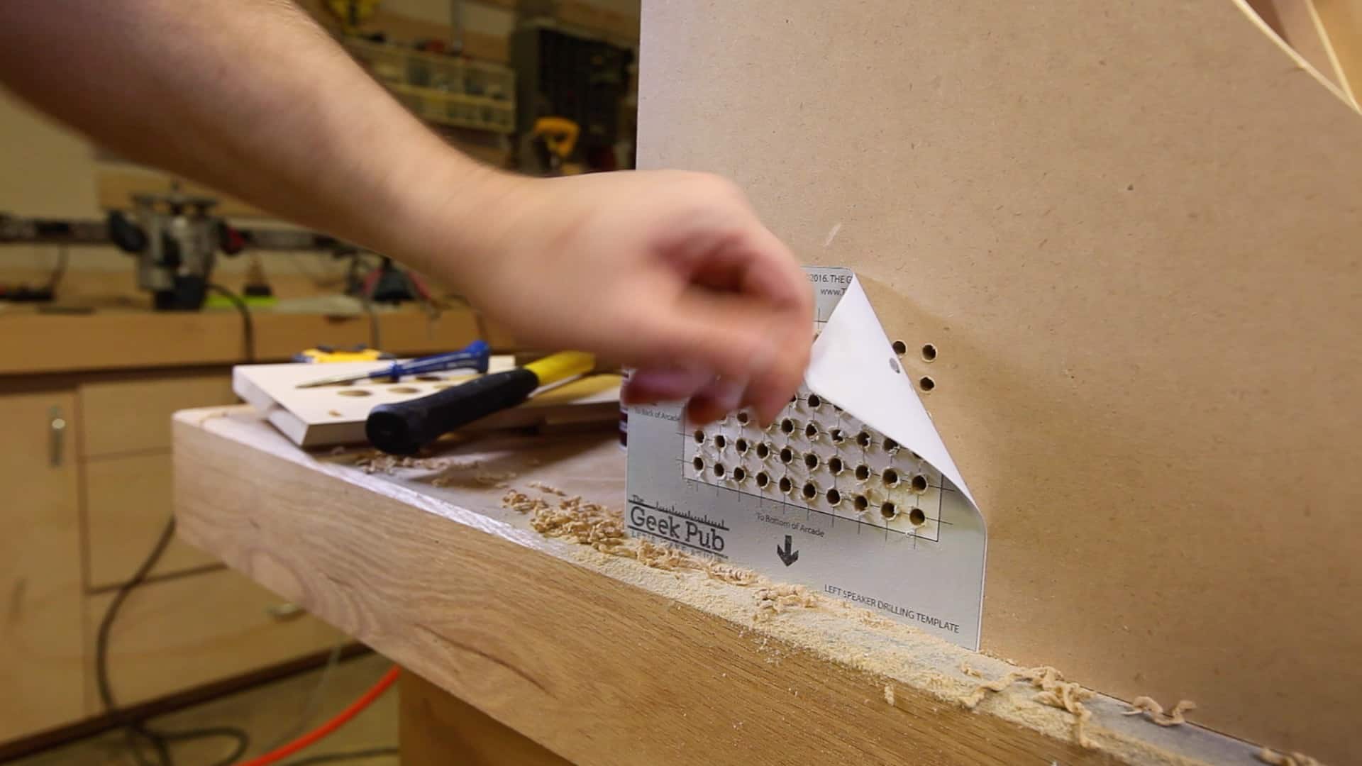
Step 10: Drill for the Speakers
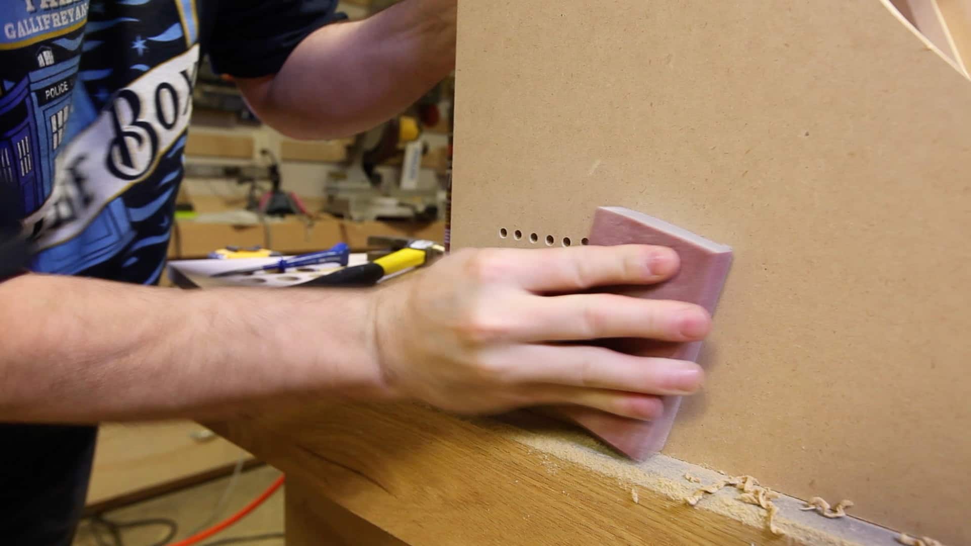
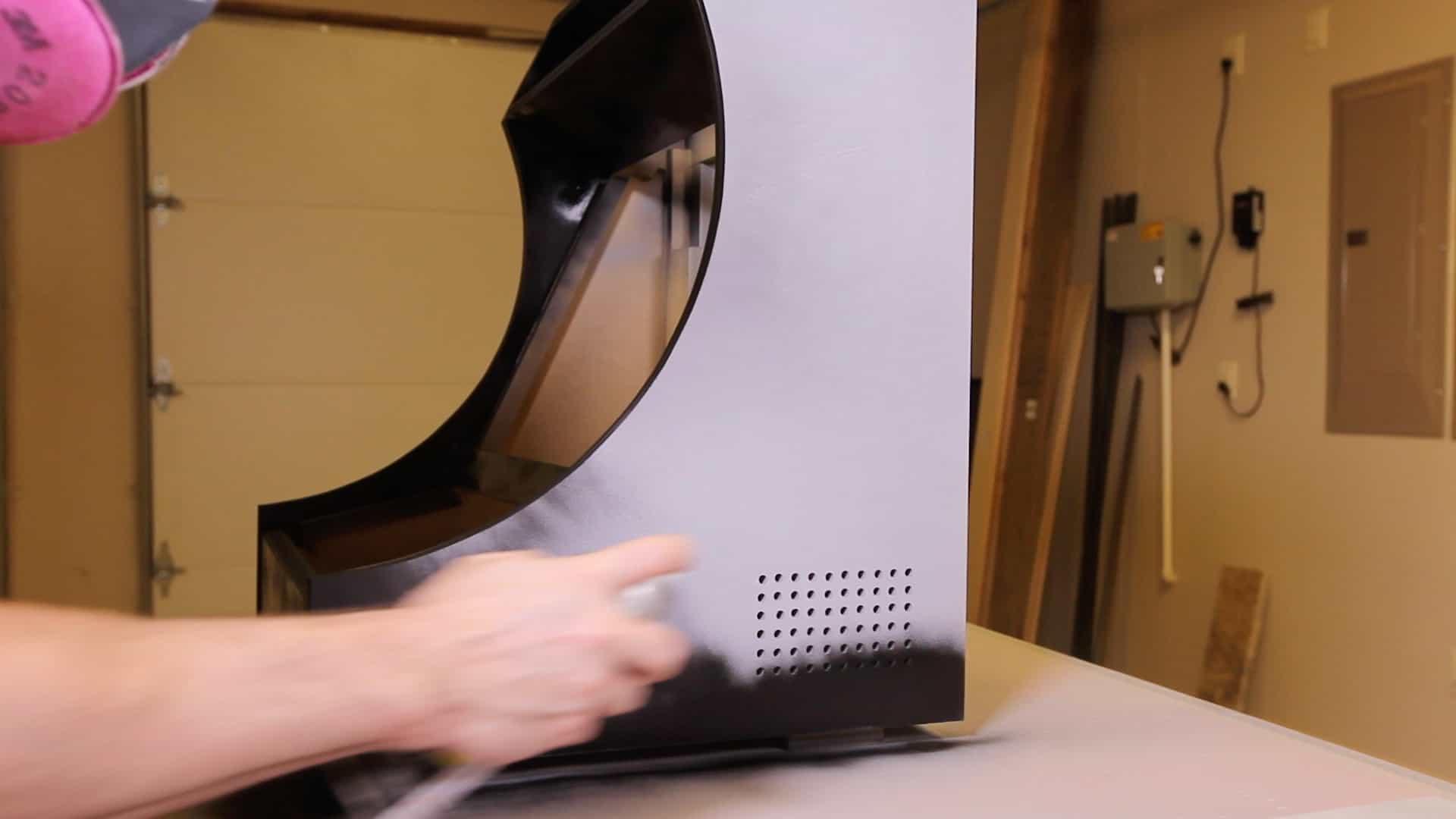
Another really hard thing to get aligned is the speaker holes. They consist of 60 holes on each side of the cabinet. I’ve included a left template and a right template with the plans. Hitting the holes with a sanding sponge will make them look like they were made at a factory.
Step 11: Prime the Bartop Arcade Cabinet
It is critically important to prime MDF. MDF by its nature will soak up paint. Ultimately MDF is nothing but glued together sawdust. I really like to use Rust-Oleum’s Filler Primer with MDF. It will fill any tiny cracks and imperfections. The only downside is that you absolutely must hit it with sandpaper between primer coats and before painting. It is worth it though because this will leave you with an incredibly smooth base to lay your paint on top of. It changes everything when painting MDF.
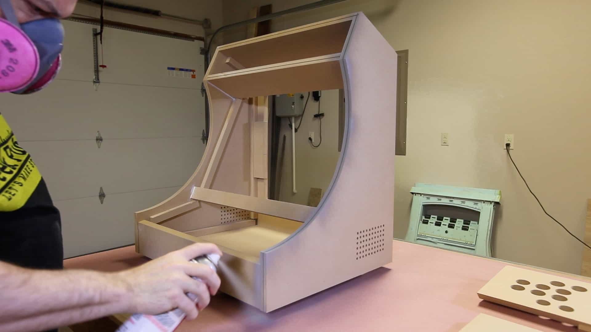
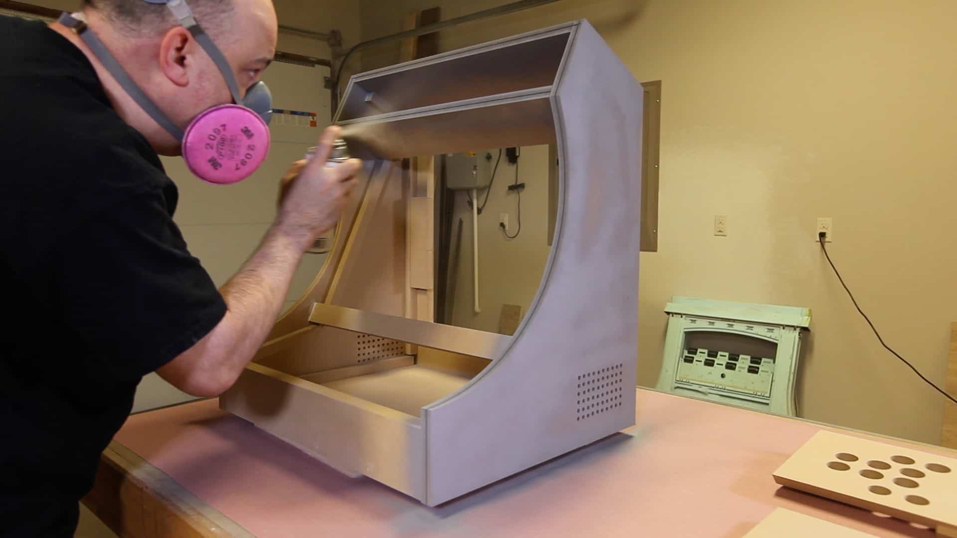
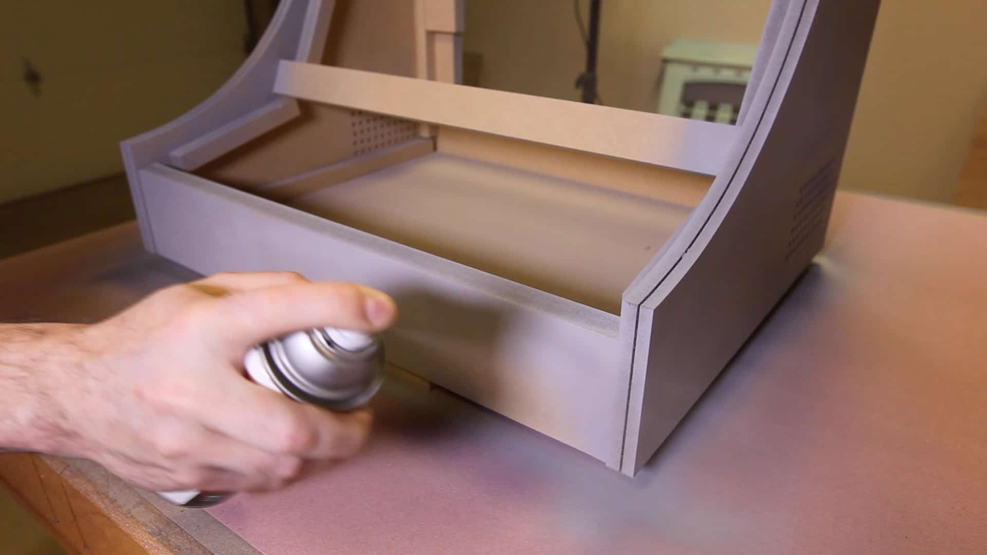
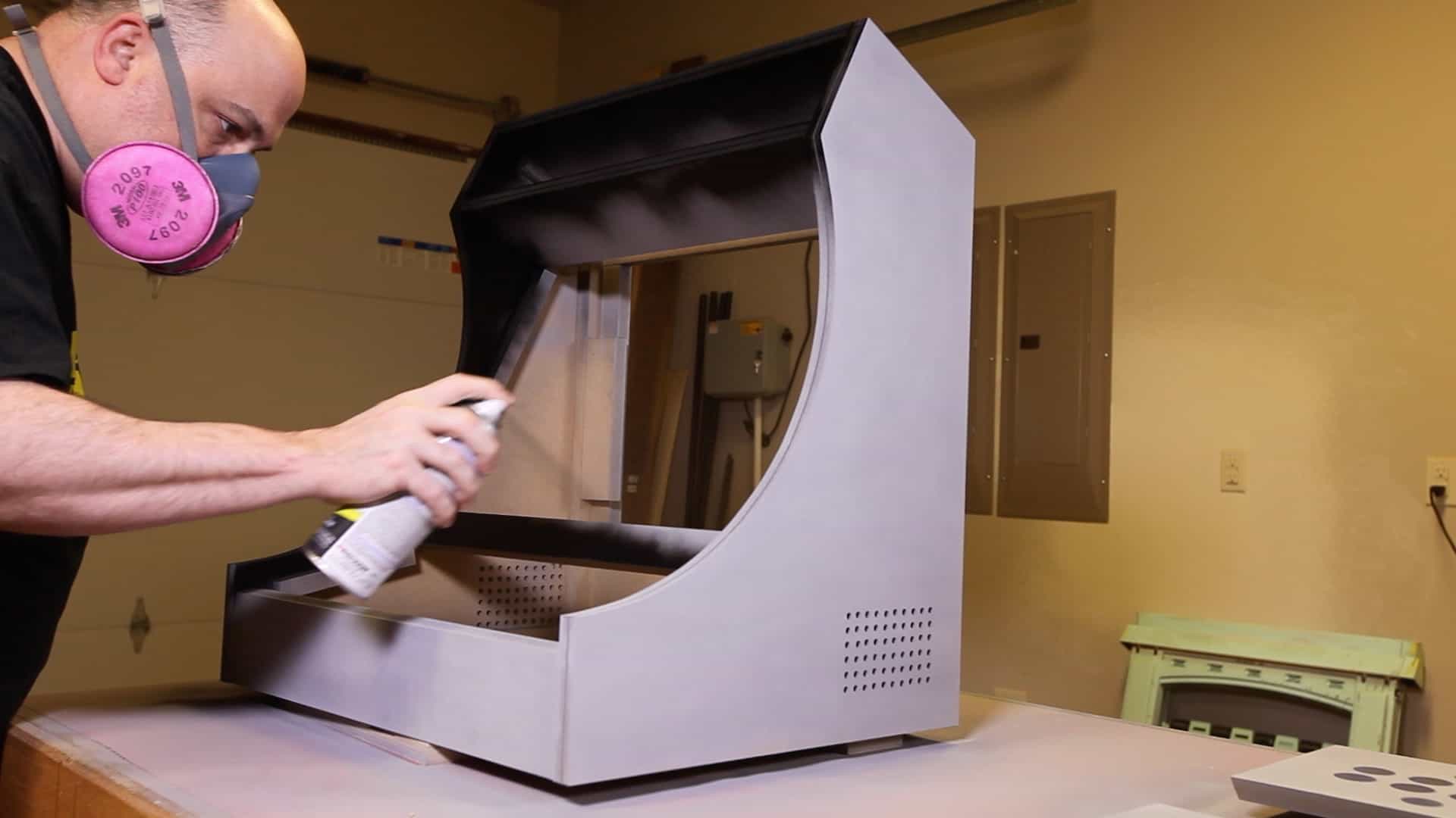
Step 12: Paint the RetroPie Cabinet
In my full-size arcade cabinet build I got a lot of comments like “Yeah, anyone with an HVLP sprayer can paint like this.” So with this build I decided to do everything with rattle cans. I can assure you the paint came out just as good.
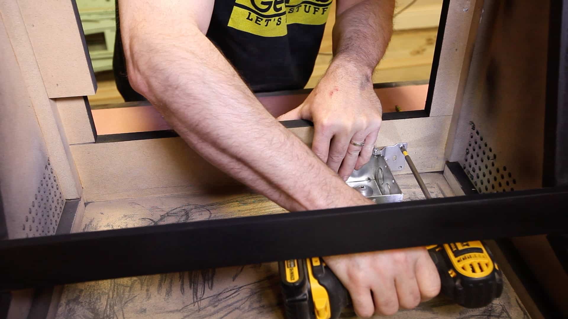
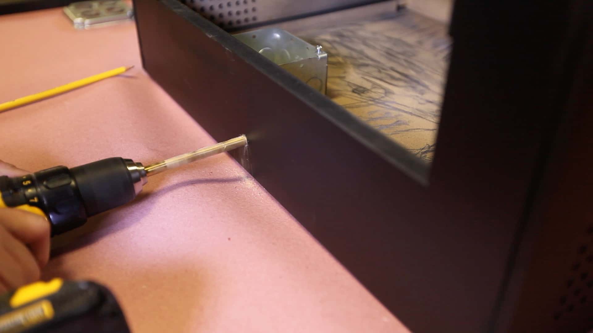
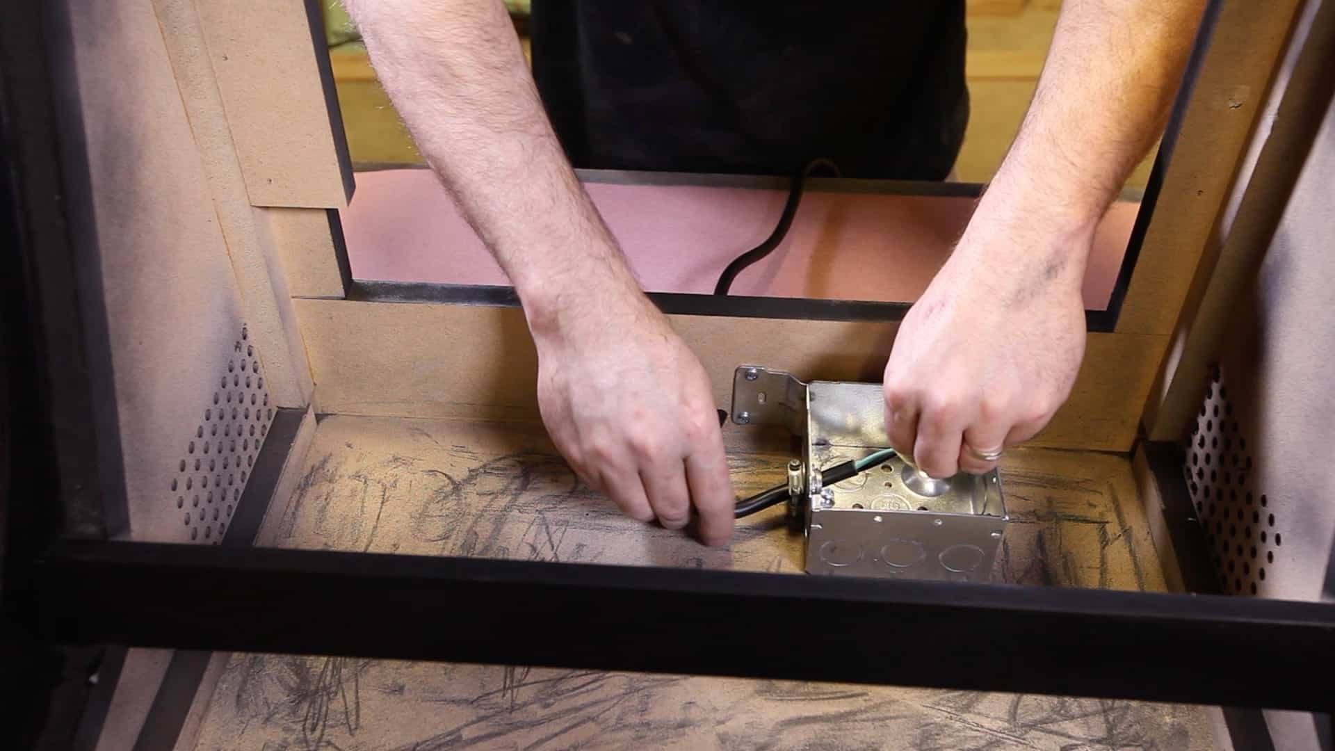
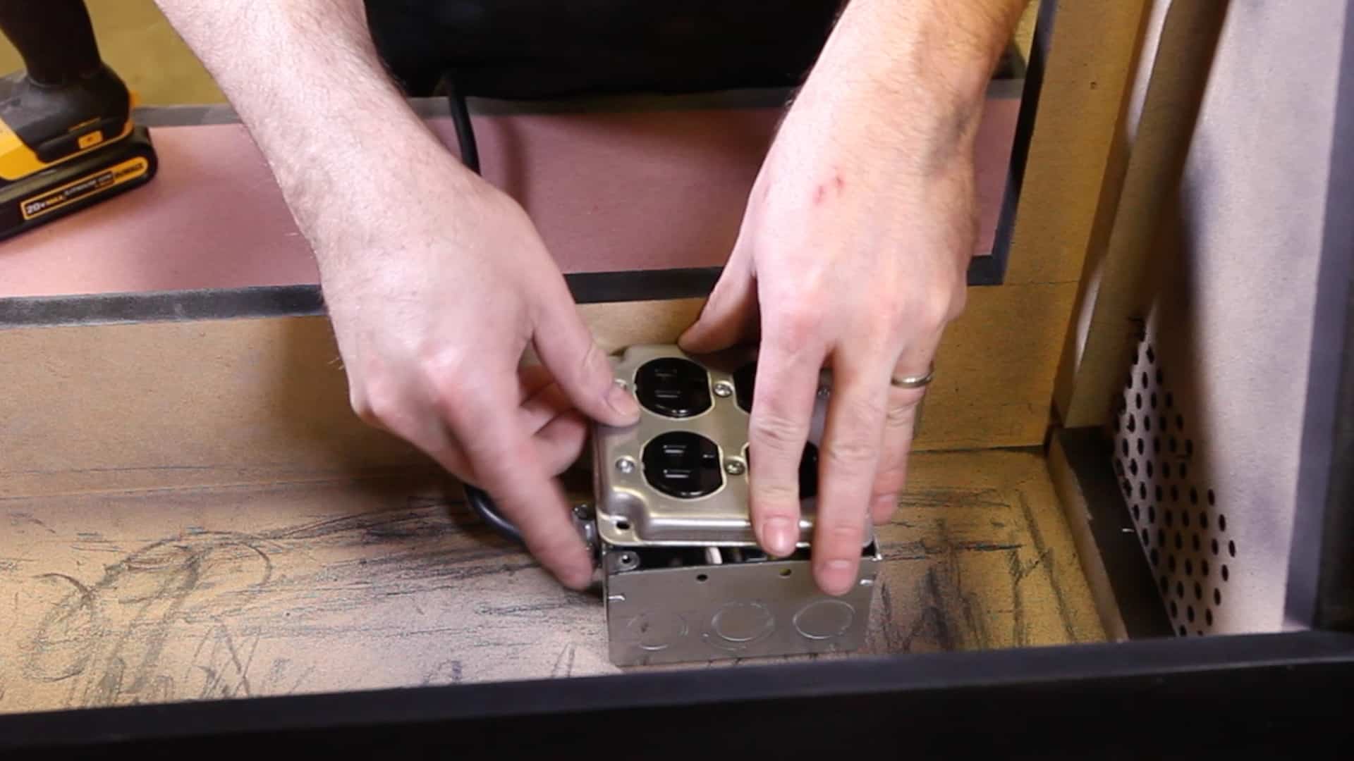
Step 13: Install the Electrical
I installed a quad outlet plug inside the arcade cabinet. This provides the exact number of outlets needed to run the RetroPie Arcade since most everything else is USB powered.
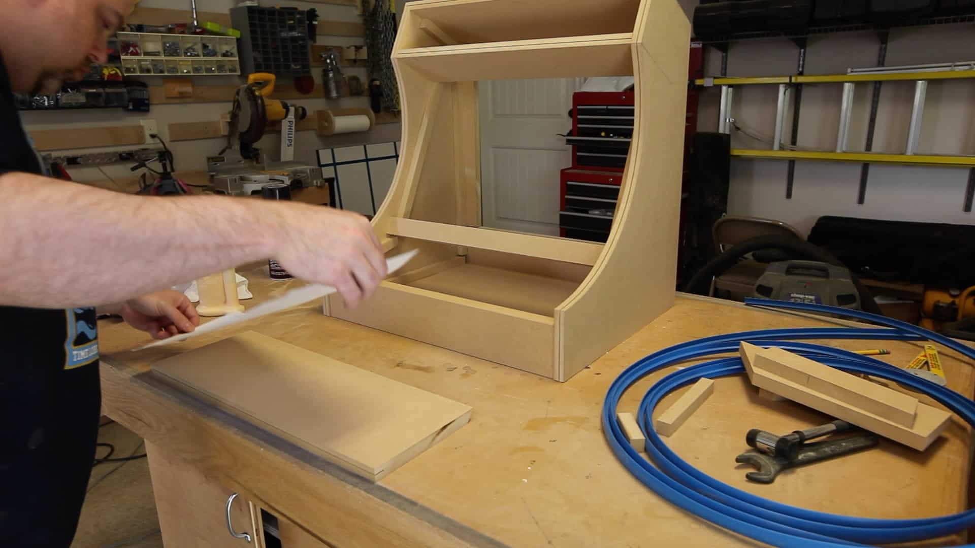
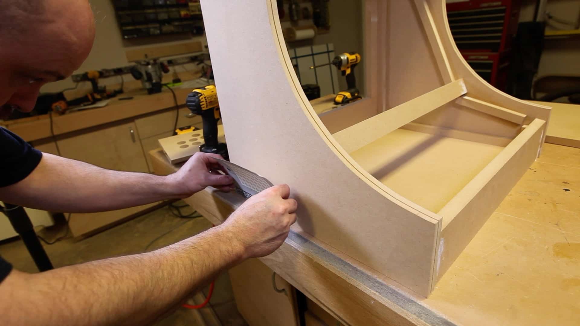
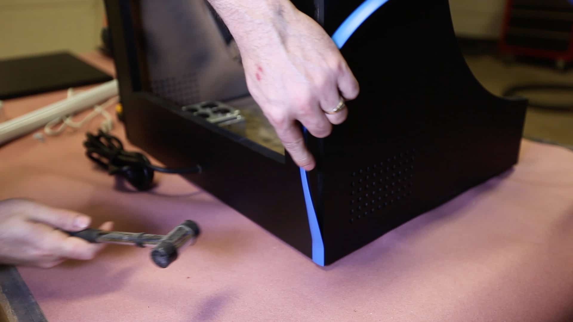
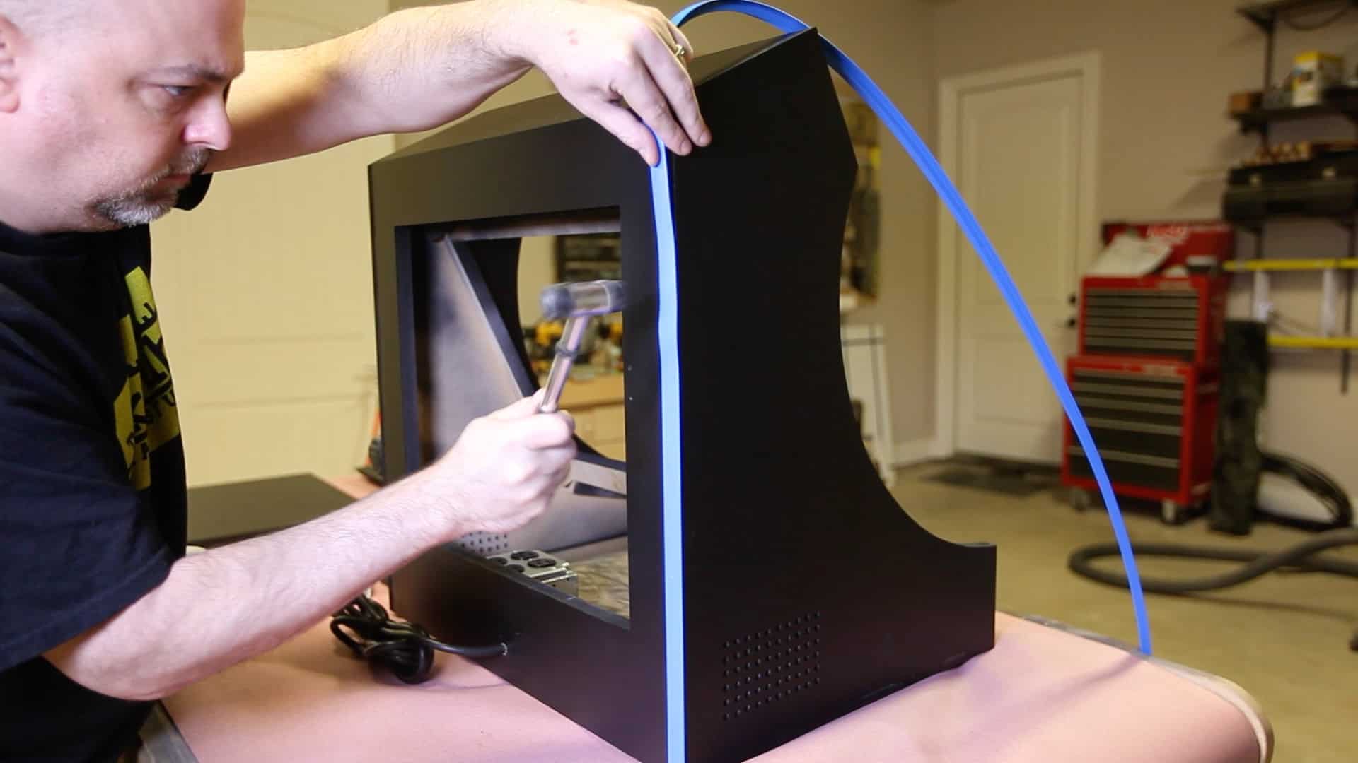
Step 14: Install the T-Molding
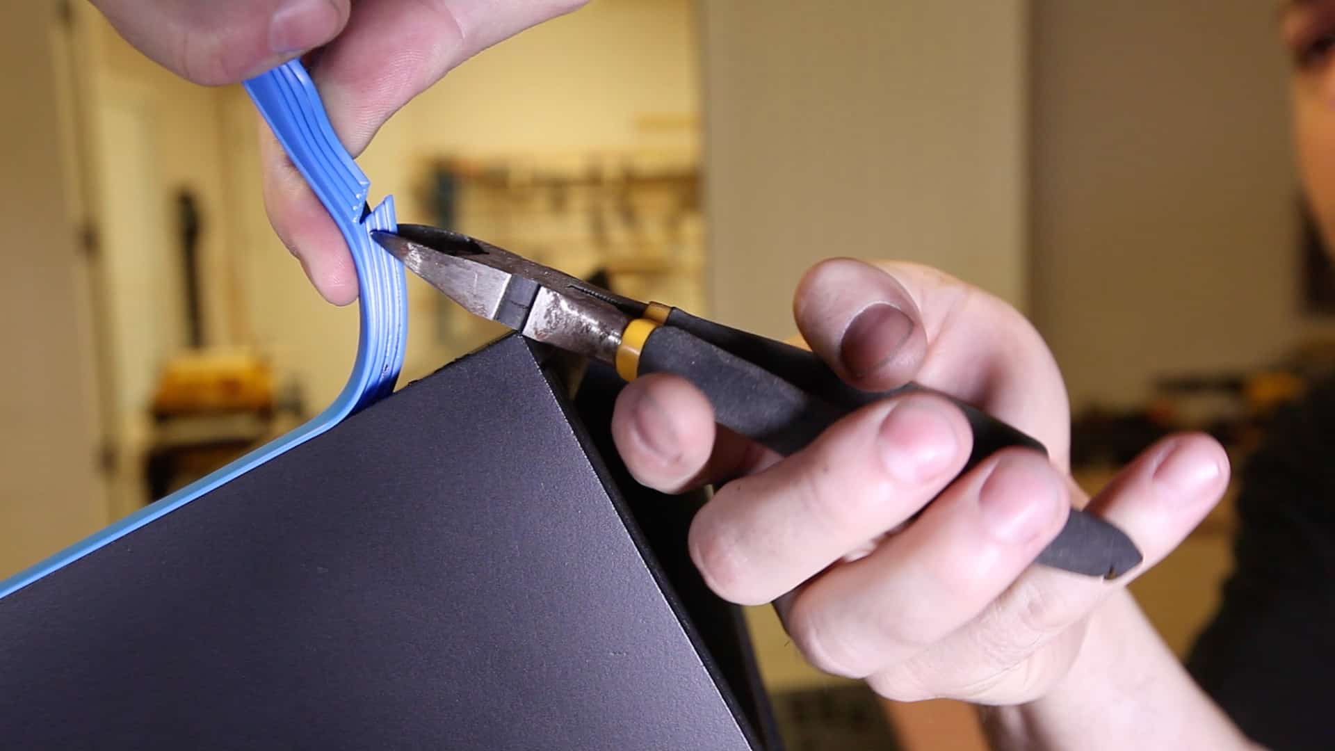
The T-Molding pops in the to T-Slots we routed earlier. I find the best way to install it is with a small rubber mallet. At the 90 degree turns you’ll need to notch the ribbed track to allow it to curve around the corners. It makes for a very clean look.
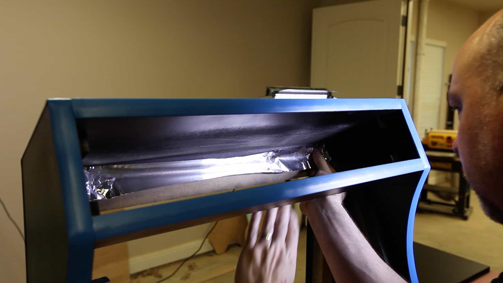
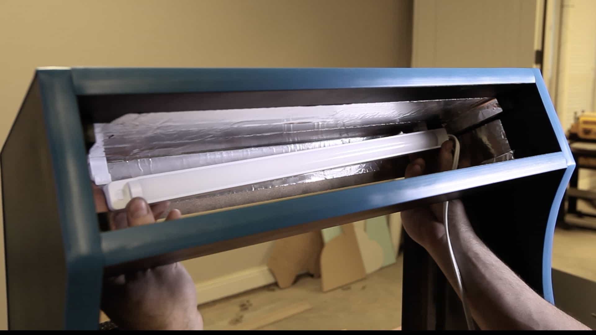
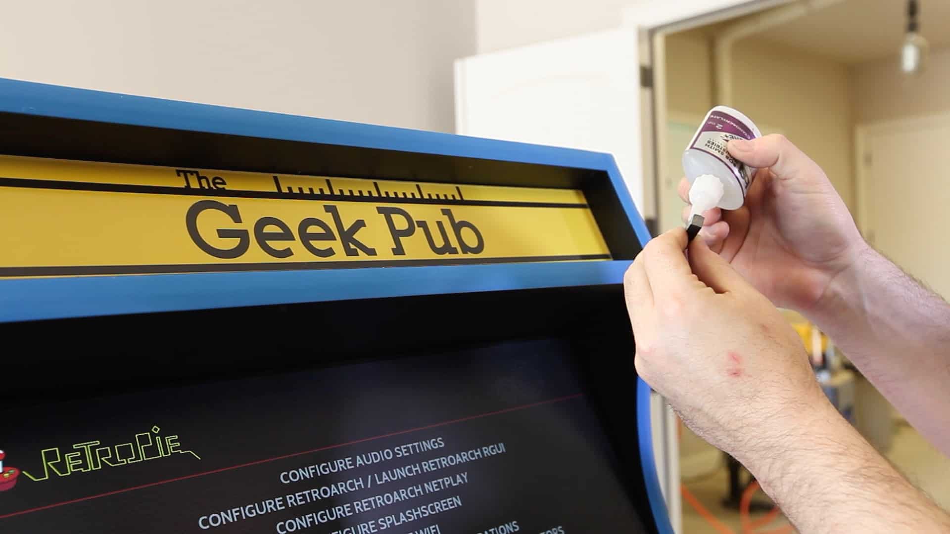
Step 15: Install the Marquee Light
I like to line the inside of the marquee’s slot with reflective tape. This makes for a cleaner look once it is lit. The LED light is simply a cheap $20 light from the local big box store.
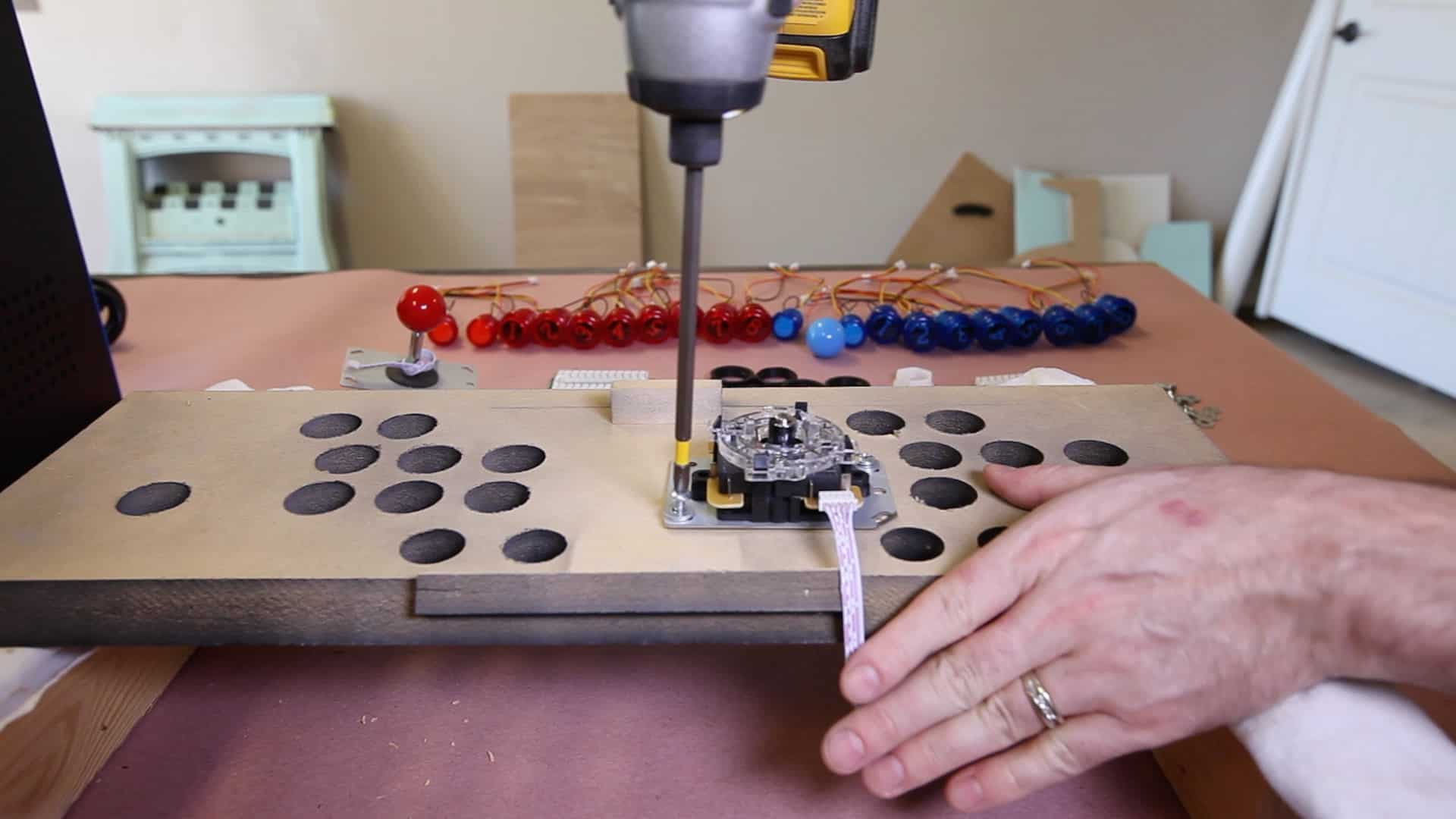
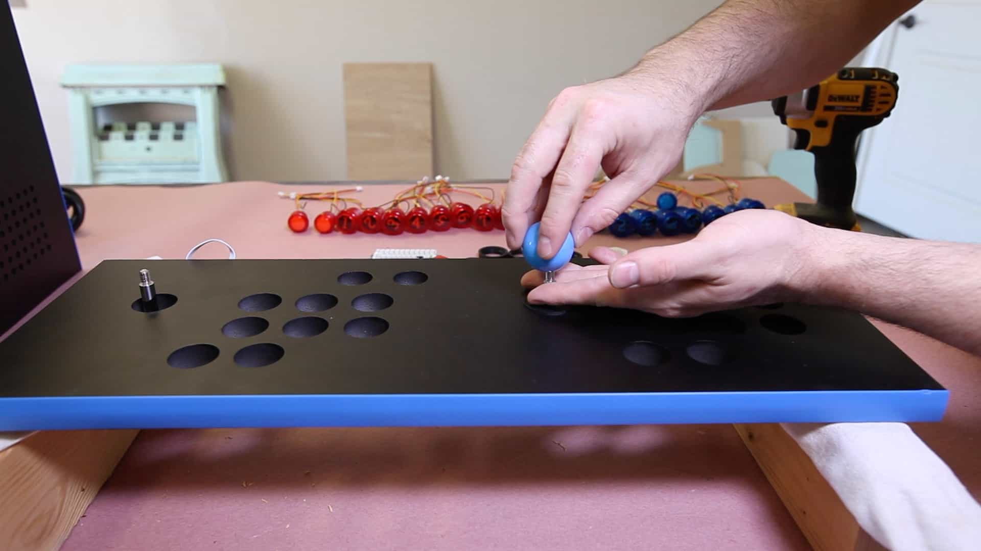
Step 16: Assemble the RetroPie Arcade Control Panel
Install the joysticks into the arcade with four screws. Install all of the buttons and screw the large plastic ring nut to the back. Then plug all of the controls into the controller boards.
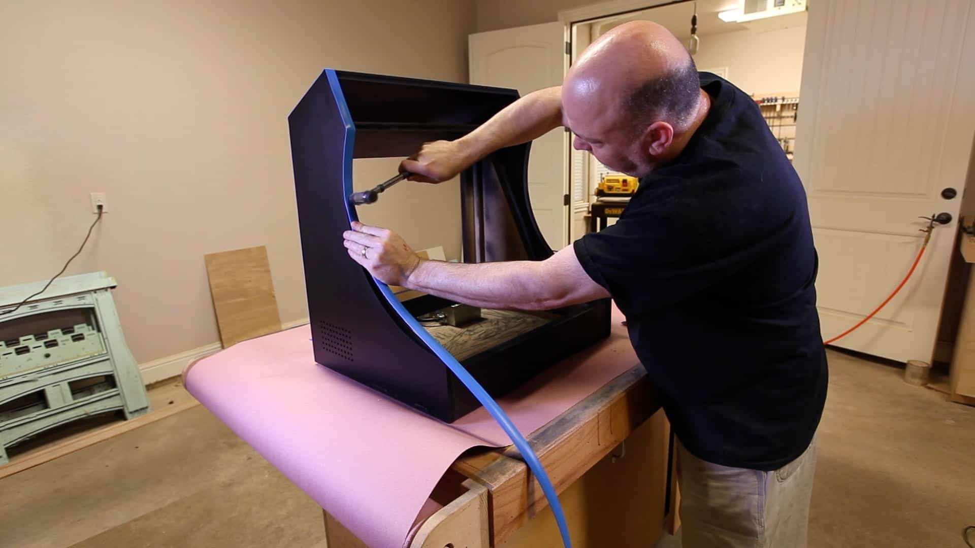
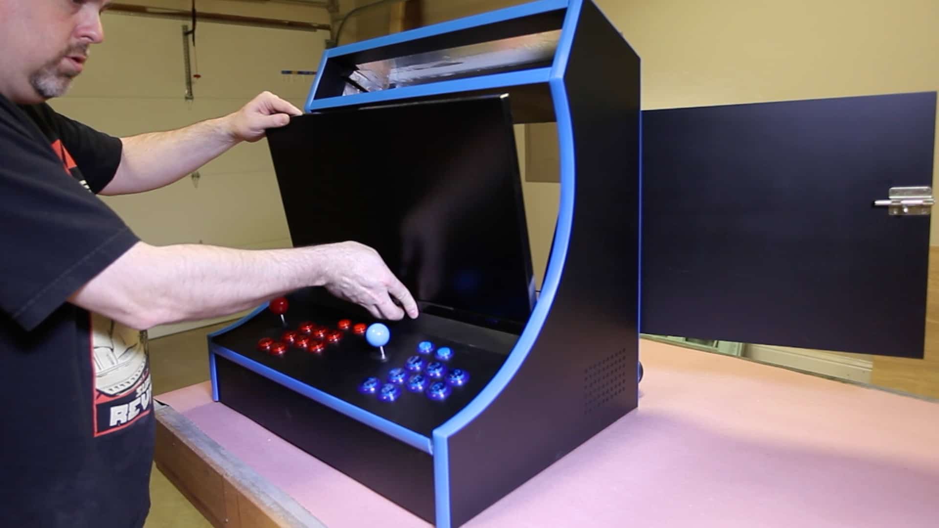
Step 17: Assemble the Major Components
Install the control panel board and install the monitor. The monitor just slides ins place and is held by friction.
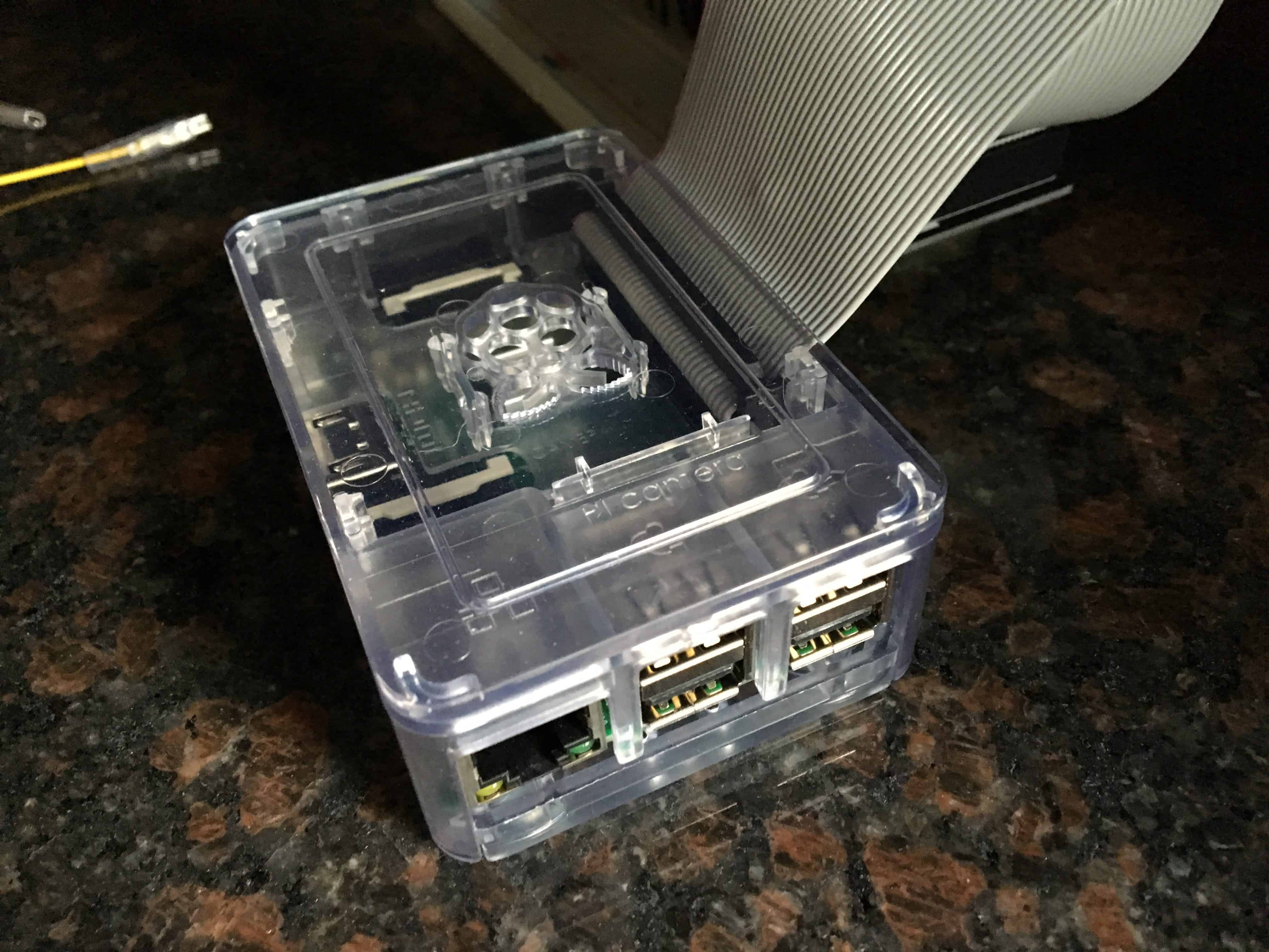
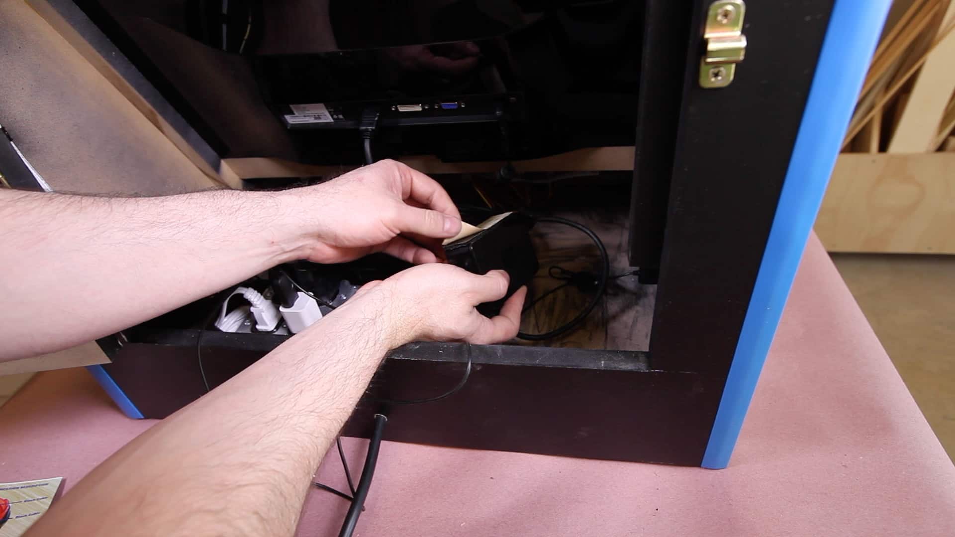
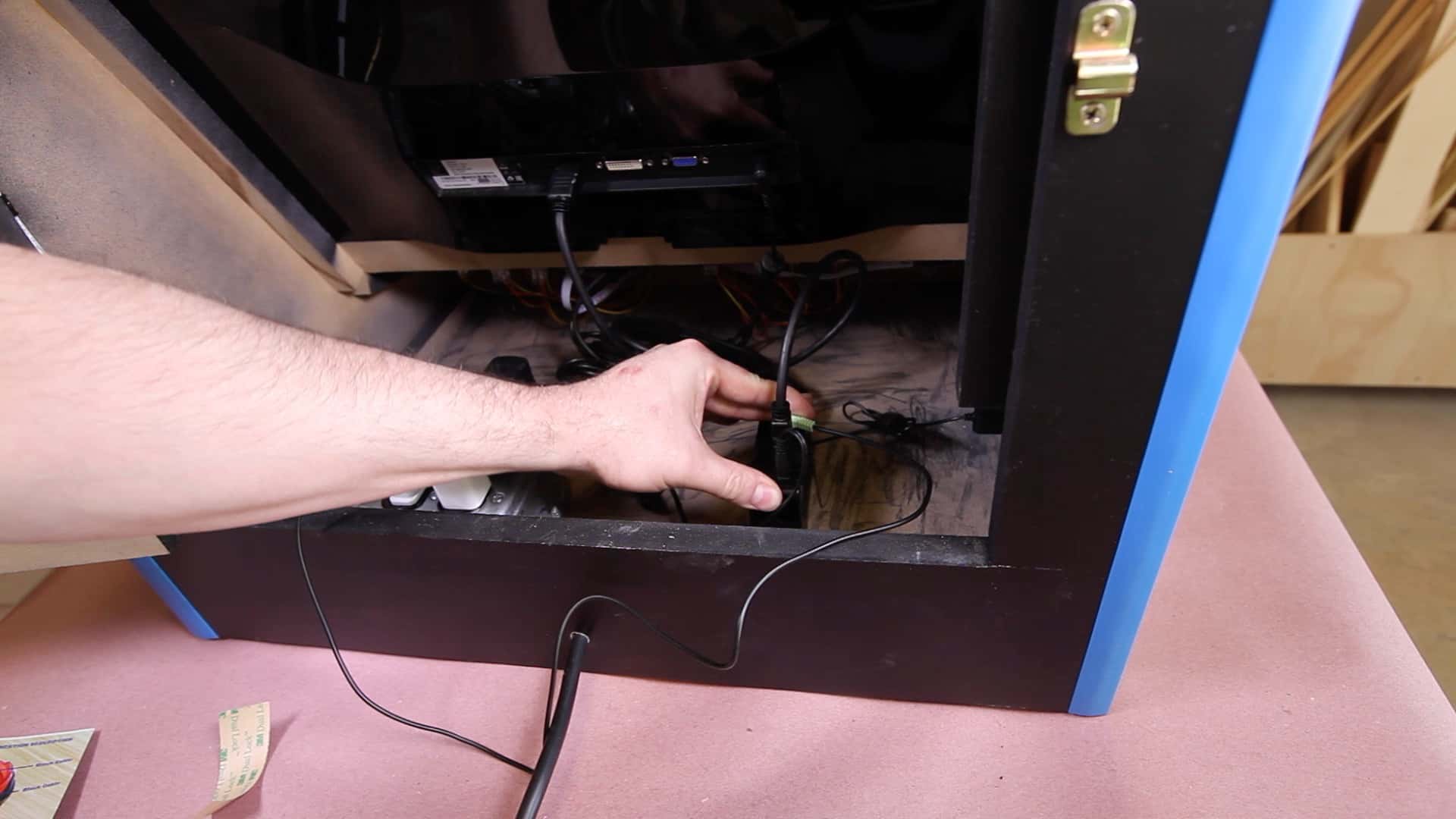
Step 18: Install the Raspberry Pi
Install the Raspberry Pi. I used an industrial adhesive backed velcro to hold all of the components in the back of the cabinet.
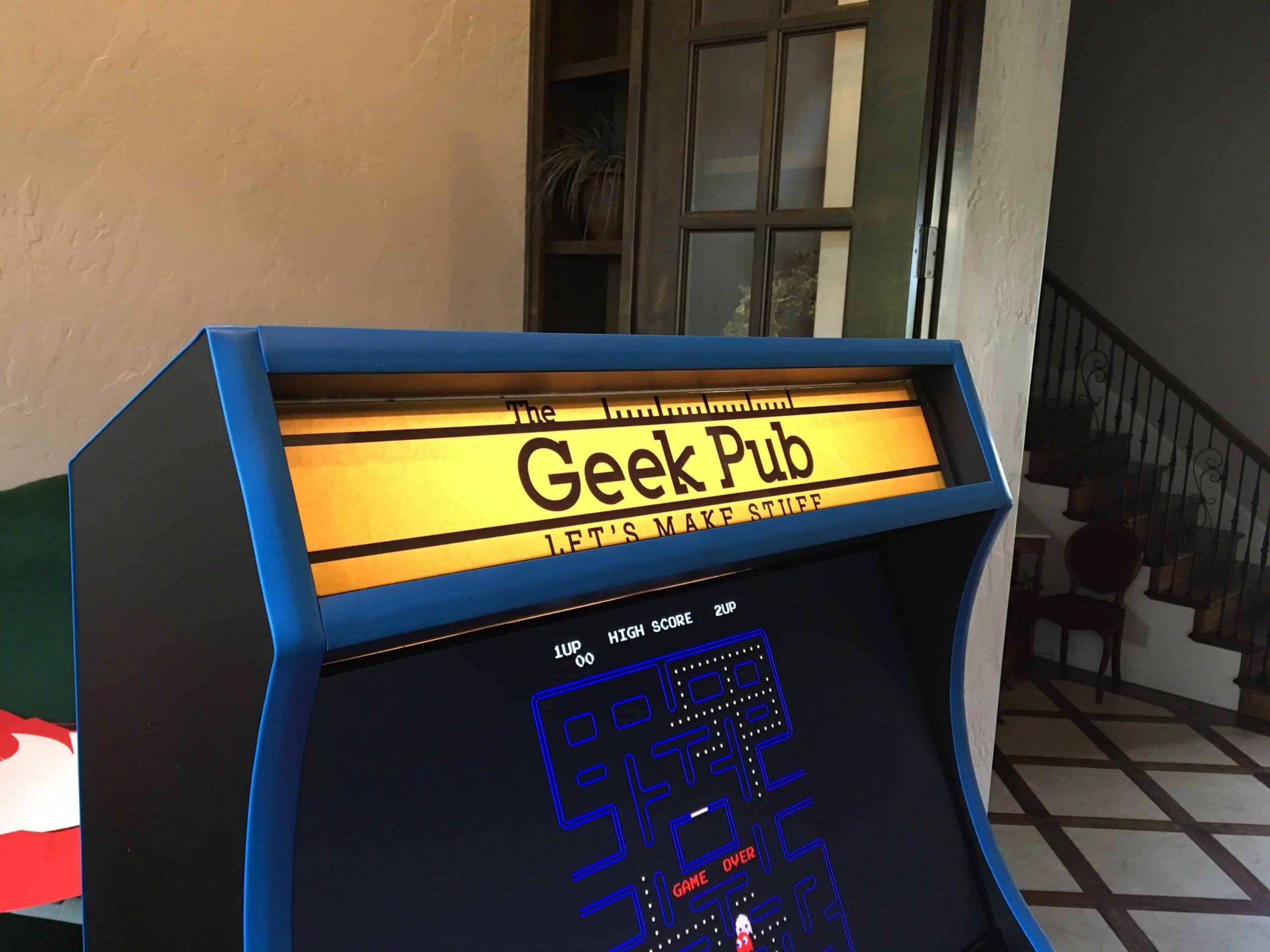
Step 19: Install the Lighted Marquee
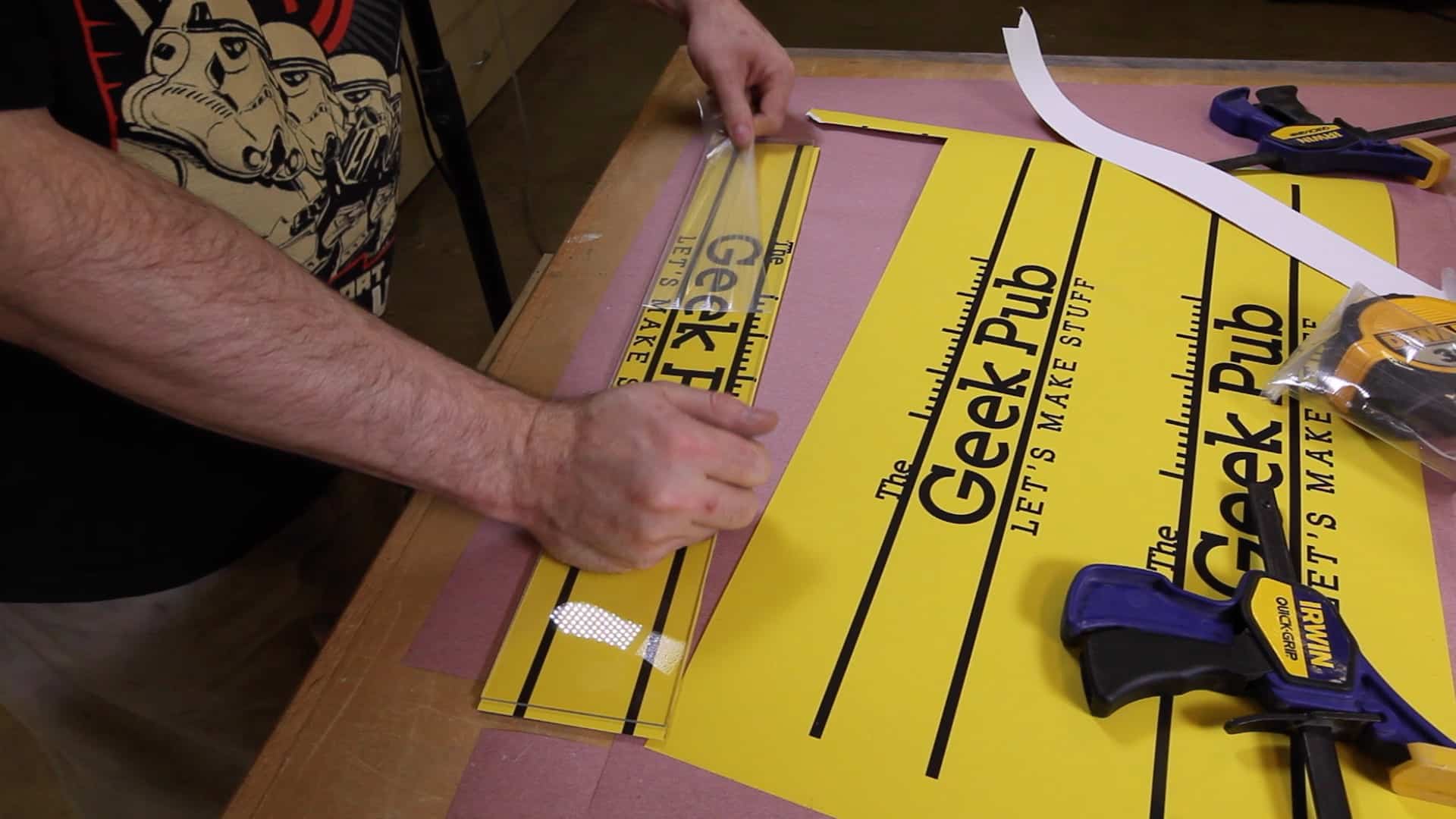
The Marquee banner is just a poster I had printed at a local office supply store for $5. It is sandwiched between two pieces of plexiglass that I cut out on the tables saw.
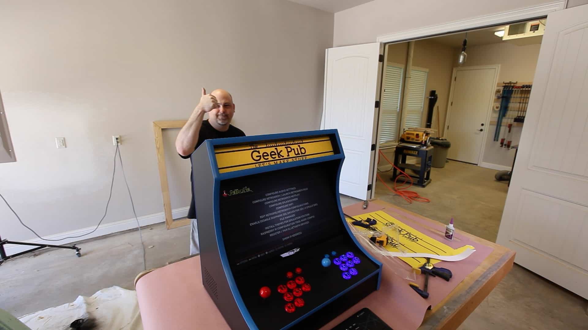
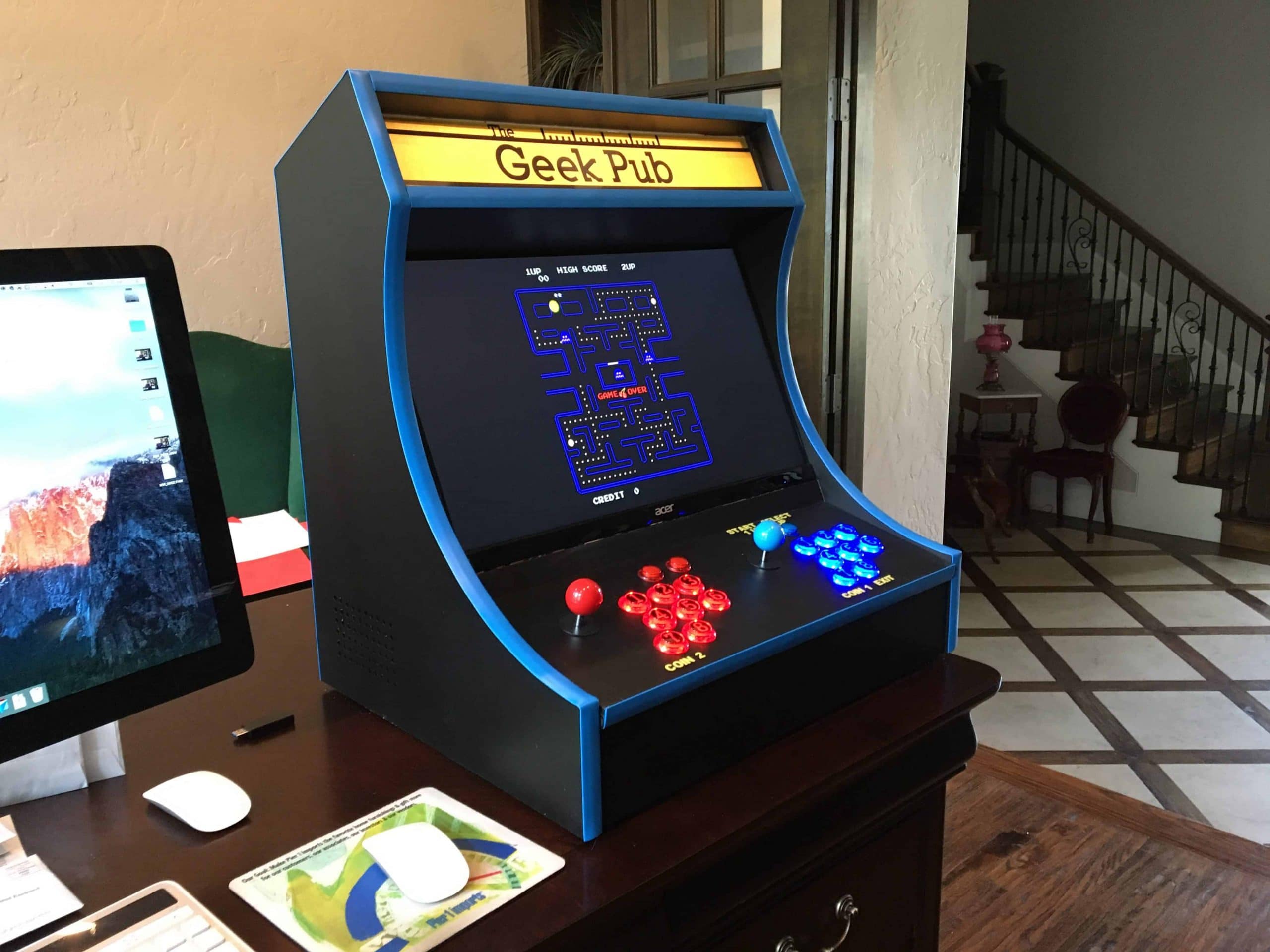
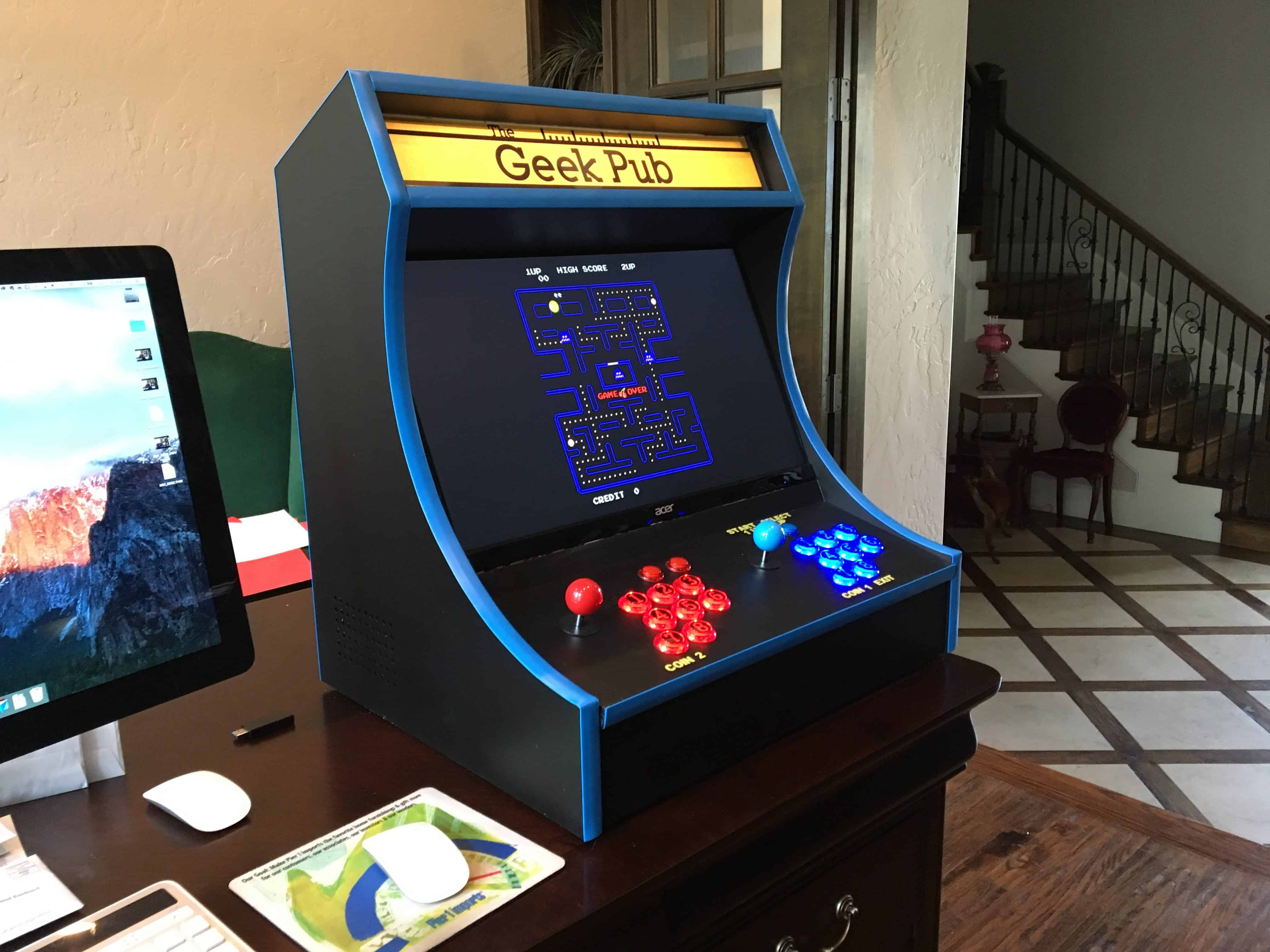
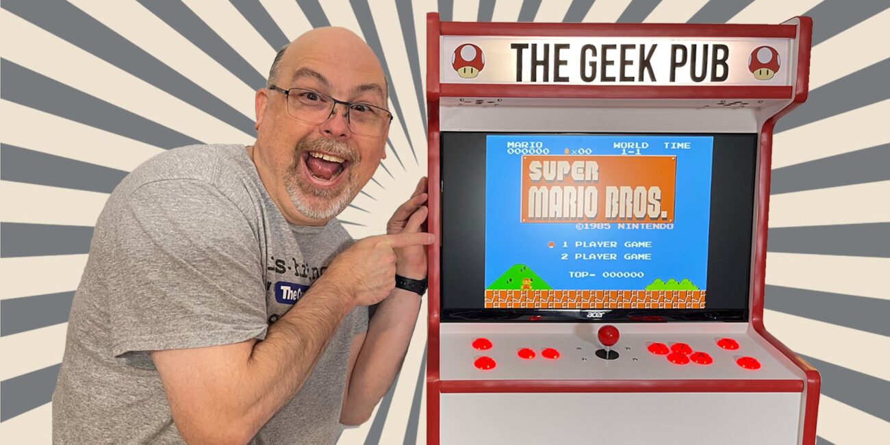
The Completed RetroPie Bartop Arcade Cabinet
The completed cabinet turned out awesome! I am super excited with this one! Stay tuned for future projects and we’ll break down some of this build into more detail, including the specifics of loading the Raspberry Pi!
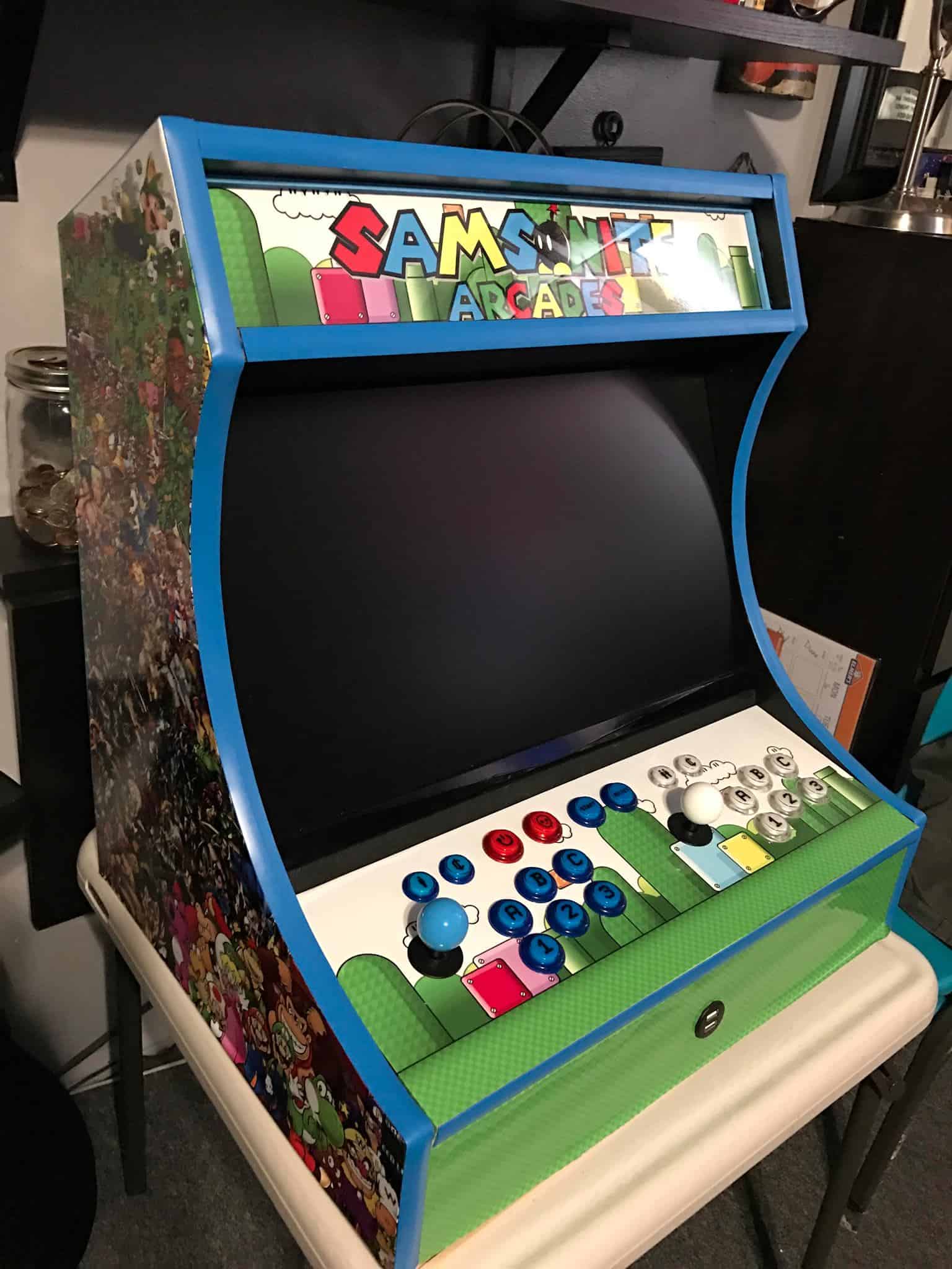
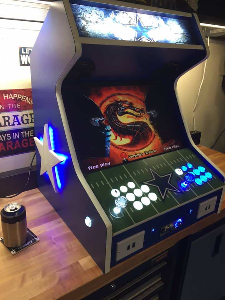
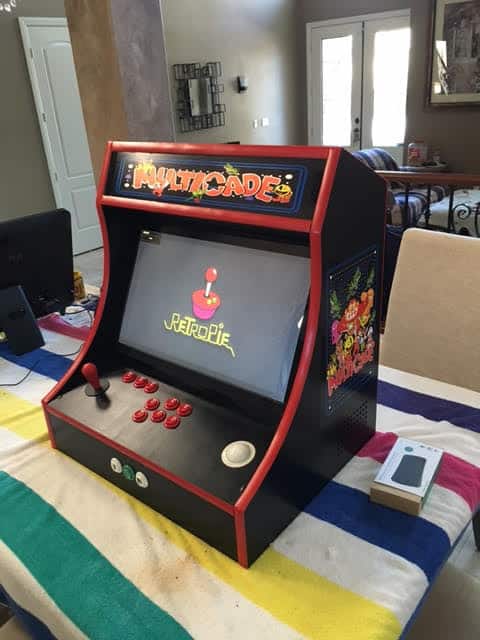
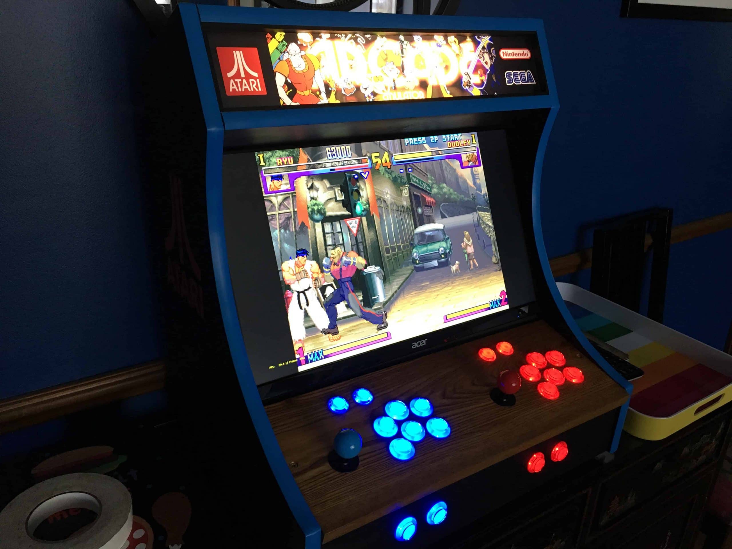
Some of our Awesome Customer’s Work
Check out some of these truly amazing looking builds from our customers, based on this set of bartop arcade plans.
RELATED: Free Play
Video Transcript
Hey guys! It’s Mike, from The Geek Pub! And on this episode we’re going to make this awesome BarTop Arcade cabinet using a Raspberry Pi!
The first thing we want to do is layout the side panels of the RetroPie Arcade Cabinet onto a section of medium density fiberboard. As alway, you can get all of the dimensions in the plans at TheGeekPub.com.
After drawing a rectangle the size of the arcade cabinet, I used my angle finder and a straight edge to transfer the angles.
I couldn’t find my square, so I just used piece of known square plywood to make a 90 degree line for the front of the marquee.
You’ll need a compass to draw the large curved section of the side panels. Rather than buy one, I just used a scrap piece of oak, a pencil, and bolt with a pointed end to make my own. You’ll need to make two tick marks from each end. Wherever they meet is the where you’ll place the center of the compass to connect the top and bottom.
I used my table saw to cut out the rectangle, and then made a second rectangle. The second one will be clamped under the first one. This will allow us to cut out both side panels in one go.
I used my air compressor to keep the sawdust out of my way. This keeps the line highly visible while I cut out the side panels of the arcade cabinet. The best rule of thumb I can give you when using a jigsaw is: Go slow! Take your time. It makes a big difference in the finished product.
Once the panels are cut, open them up on the workbench like a book! You’ll have two identical side panels for your arcade!
I cut out a bunch of sections of 3/4 X 3/4 inch MDF to use as connection points inside the bartop arcade cabinet. These are inset exactly 3/4 inches. This not only makes the assembly of the arcade cabinet easier, but has the benefit of leaving no exposed nail heads or screws on the outside of the arcade cabinet.
Where appropriate, rather than measuring I simply used spacer of the right size. This ensures my spacing will be dead on accurate. You can cut these spacers from scraps. Simply pull them out and discard them afterwards.
You can use also reuse the spacers as angle finders and place holders when gluing and nailing in your connectors.
The next step is to glue and brad nail the side panels to the top and bottom panels. Be sure to make sure everything is square. If you don’t have a brad nailer you can use screws or just use clamps and wait for the glue to dry.
The 3/4 inch connector pieces we put in earlier make assembly super simple. All you have to do is add glue and line everything up. Again, I am using brad nails to speed up the process. The brad nails are simple there to hold everything together long enough for the glue to dry.
I love the retro look of T-Molding on arcade cabinets. In order to install T-Molding, we need to cut a T-slot in the side panels and all of the components. You have to do this before final assembly as the router will not reach everything after assembly.
Now that we’re done with the routing, we can simply install the remaining panels. We’ll start with the bottom panel of the marquee.
This board will be the bottom frame of the LED monitor.
Then we will install the front of the control panel. This board is slightly inset for a 3D appearance.
On the backside we just need to frame in where the access door will go.
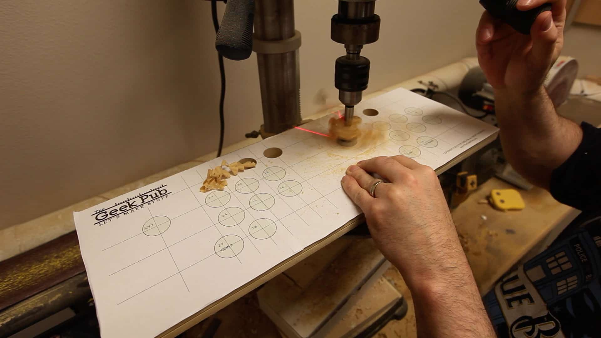
I created this awesome drilling template that you can get on TheGeekPub.com. Just lightly coat the back of it with spray adhesive and press it to the control panel. Using the template makes it super simple to drill out all of the holes for the joystick and the buttons. It’s also a fantastic reference sheet for install the buttons later.
I used my drill press and Forstner bit to drill out the holes, but you can use a handheld drill and a paddle bit in a pinch.
Once you’re finished, just peel the template off and discard it.
I cut a section of MDF the exact size of the access panel in the back of the arcade and installed it using a piano hinge and a small latch. This will allow future access to inside of the cabinet for maintenance reasons. I used a couple of paper spacers to center it and my square to make sure everything would open and close easily.
The arcade cabinet has two speakers, one on each side of the cabinet. Provided in the plans is a drilling template for each side to make drilling the 120 holes much simpler. Just attach them with spray adhesive. And then get ready to drill and drill and drill and drill.
When your finished drilling, just remove the template and use a sanding block to remove any burs, it will look like it was made in a factory.
The next step is to prime the MDF. Primer is critical if you want an awesome finish. When I prime MDF, I like to use filler primer as it fills in all the little imperfections. You’ll need to sand it with 220 grit sandpaper before you paint it though.
In my full-size arcade cabinet everyone told me that it was easier because I had an HVLP sprayer, so for this cabinet I am using rattle cans from my local home improvement center. I decided to go with flat black.
With the cabinet laying on its backside, I installed some polyurethane feet to keep the cabinet from sliding around not he table.
I installed an electrical box in the back of the cabinet and then drilled a hole to accept the power cord. This will be the electrical system for the entire cabinet.
In the electrical box I installed quad outlets, exactly the number of plugs necessary to power the RetroPie Arcade!
The next step is to install the T-Molding. I find the best way to get a smooth finish is to use s small rubber mallet. Take your time and go slow and the results will be fantastic.
When you get to one of the 90 degree cuts you’ll need to cut the track section of the T-Molding to allow it to bend around it. This really makes for a nice seamless look.
In order to make the lighted marquee more uniform in appearance, I like to line the inside of the marquee with reflective tape. Once that’s done I install an 18 inch LED light from the local big box store.
Installing the controls is very simple. Each joystick requires four screws, i recommend pre-drilling these to make sure they sit flush.
The tops of the joystick have a black washer to cover the hole and then you just screw on the balls.
Then its just a matter of inserting all of the button into their respective holes.
On the back of the board you just install a large plastic nut on the back of each button.
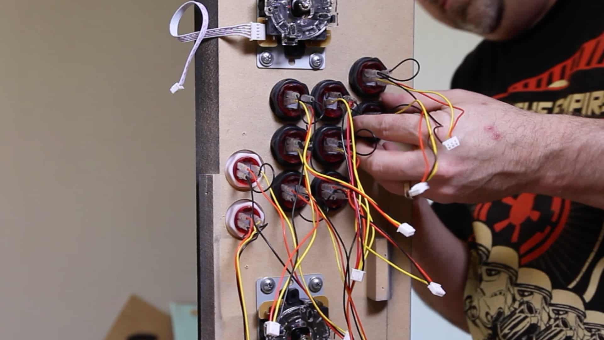
Now it is just a matter of plugging every button into the correct socket on the controller board.
I love these USB powered speakers because they fit perfect in arcade cabinets and don’t take up much room. I just use hot glue to hold them in place, and they be easily removed with a heat gun.
This is where the really fun part begins. Final assembly! Start by popping the controller board in place and and installing the monitor.
I like to use this industrial adhesive velcro to hold the components in place. It allows you to easily remove them later for maintenance but will last forever.
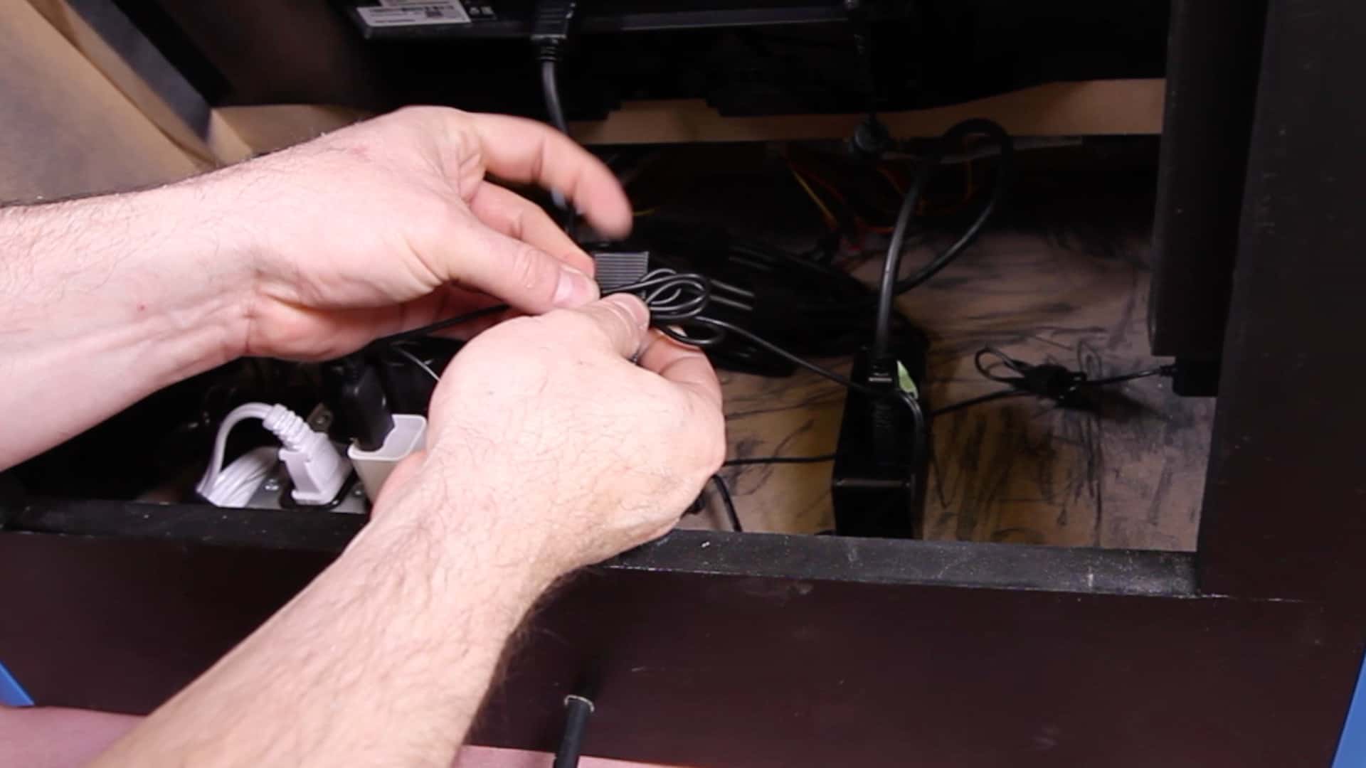
For cable management I use this two sided velcro stripping to roll up the wires.
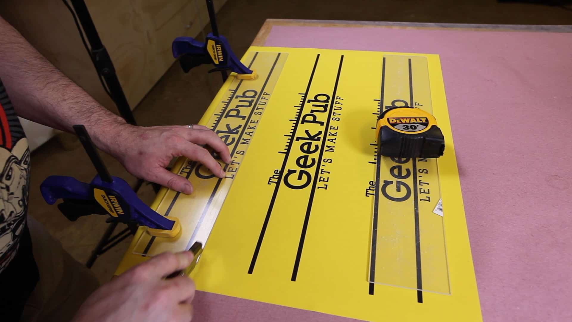
You can get your marquee printed at any office supply store’s copy center for about $5. Then you just need to cut it to fit the size of your marquee. You’ll sandwich it between two pieces of clear plexiglass. Don’t forget to peel off the clear plastic protector it comes with.
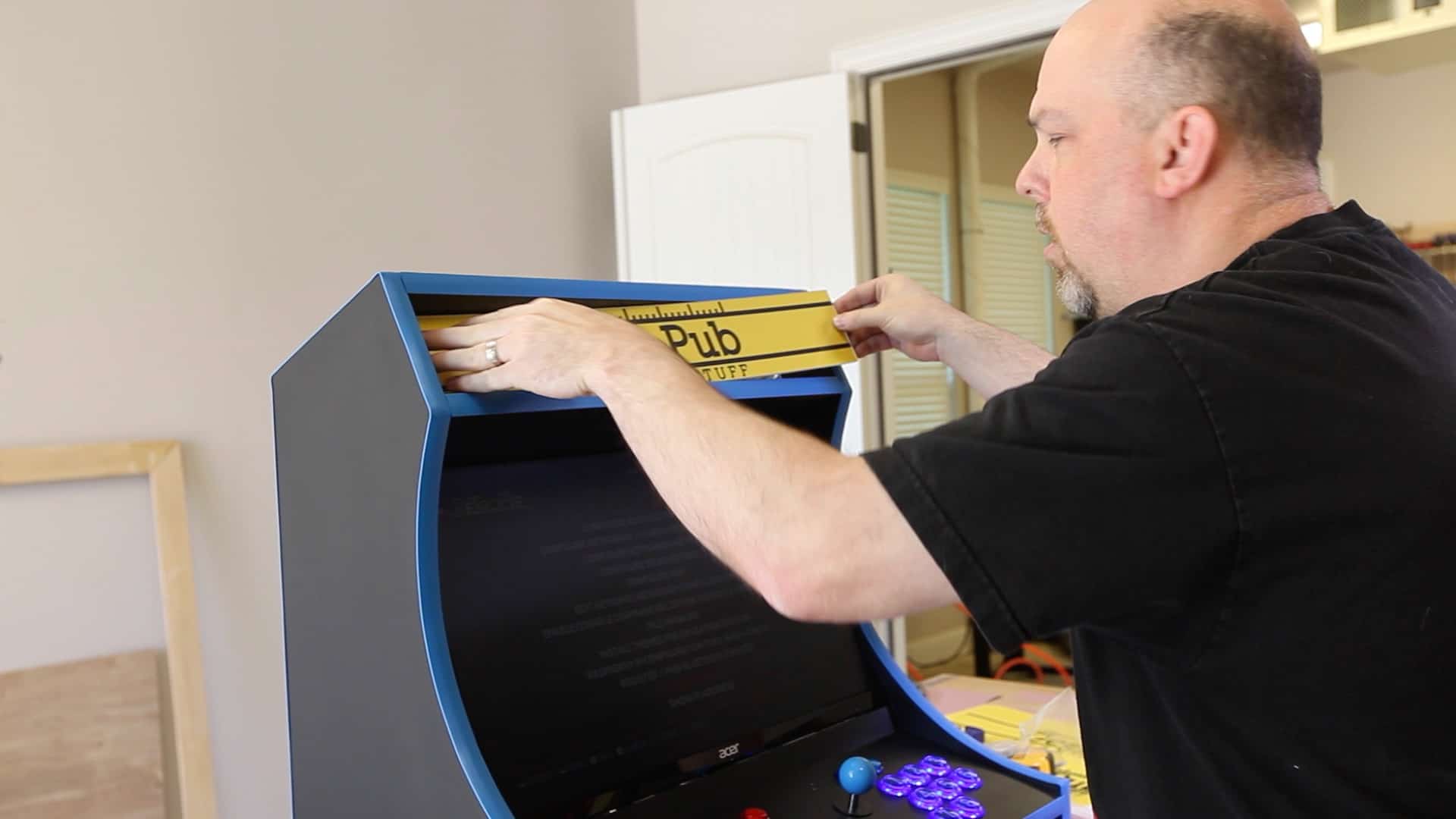
The marquee banner just drops into place.
To keep it from coming out I just glued in two small 1/4 inch pieces of MDF that I pre-painted black.
The last step is to plug in the LED light!
OK! Well I think this cabinet might have been more fun than my full-size arcade cabinet and the reason why I think is because I used a Raspberry Pi. Now a lot of you are probably asking “Why did I use a Raspberry Pi?” Well the first reason is very simple. It costs $35 dollars. Literally anyone can afford to buy a Raspberry Pi! The second reason is RetroPie. So RetroPie is preconfigured. You just download it from their website. There’s no configuration trying to figure out how to get some front-end to work or some game to work. You just download the entire RetroPie image and load it on your Raspberry Pi and you’re done. You’re ready to go. All you have to do then is drop your game ROMs on. The third reason is that the Raspberry Pi has GPIO. Now I did not use any of the GPIO features on this cabinet. But if you wanted to have a game say where if you crashed, the cabinet would shake. Using the GPIO off the Raspberry Pi would make that incredibly simple. And then finally the fourth reason is no cooling. So the Raspberry Pi puts off almost no heat. So you can put the Raspberry Pi in here with no fan and you are ready to go. If you wanted to use a PC in this cabinet instead of a Raspberry Pi I would probably just add a fan to the back door and plug it into one of the USB ports.
Well guys, stay tuned for some future videos, because we’re going to break this down a little but farther. We’re going to talk about the Raspberry Pi and how to load RetroPie and some of those other things as well as how to connect the control boards in a lot more detail. So look for those coming up.
Well hey be sure to follow me on Facebook and Instagram. That’s Facebook.com/TheGeekPub and Instagram.com/TheGeekPub. I post pictures of all of my projects as I build them, so you get a sneak preview of what’s coming in the next video. Also consider becoming a patron on Patreon by clicking this link here. That will help me fund projects like this and I can make more videos. See ya next time.


Any regrets on the location of the buttons on the control panel? It looks like you could accidentally hit the “Exit” game button while playing a game that uses the 6 buttons. I haven’t drilled out the control panel yet so that’s why I am asking. Perhaps I should relocate some of the admin type buttons to the bottom front of the control panel. I was also thinking about adding a button on the left and right side for pinball style games but I’m not sure yet. This is my first time building anything like this so it’s all new to me. Thanks.
On my full size arcade I put buttons on the side, and I have used them exactly zero times. Hence why there are no side buttons on this cabinet. I’ve not experienced any issues with the layout, but feel free to change it up any way you like and make it your own.
Thanks Mike. To be honest I probably wouldn’t end up using the side buttons either. I might just leave the layout the way you have it, I just wanted to check with you first since you’ve had time to play the arcade and would have noticed if they were a problem or not. Right now I unable to find anywhere in my city that sells a 1/16th slot cutter bit for my router. So I can’t cut the slot for my t-molding and assemble the rest of the cabinet. I was hoping to paint it this weekend. Oh well, it looks like things are going to be delayed while I order one online. : (
Oh, I had a question about the width of the back door. I probably screwed something up but the plans show 17″ wide but when I tried to test fit the door after I was about 3/8th too short. The 14 1/2″ height was perfect but the width of my space was 17 3/8th. Did I screw something up? No big deal, I have a scrap piece of wood and so I’m going to recut a new piece to fit. Or I might just knock out one of the 2″ side door pieces and make it 2 3/8th instead.
One final question. I am going to order the same arcade kit as you and was wondering about what size of Forstner bits to buy. Is it 1″ and 1 1/4″ for the buttons and joystick holes?
Were Do you get the games from?
I can’t tell you. If you don’t understand why I am sorry.
Great plans and build video. I have the Dragonrise sticks and buttons from easyget. I find that after exiting a game (doesn’t matter which console), usually the 2nd player will have the up/down/left/right setting reversed. I will go back into input configuration and remap them but the same thing occurs again. (I am running 3.8 The controllers were bought from amazon. They are plugged into ports 0 and 1 on the pi.)
I’ve not seen this problem, but I suspect its a mapping issue in your retropie config file. First thing I would do is just reset the config to defaults and then re-add the sticks.
Oh. And assuming that its not just reversing any setting, you could always just reverse the cables on the up/down axis on your stick.
How do the speakers sound when placed on the side like that? Most cabinets I see have their speakers up in the marquee. However, I screwed up my project a bit and I don’t have room in the marquee for speakers, so I’m looking for alternative placements. The cab looks fantastic, by the way.
They sound fine. I did put the speakers in the marquee in my full size unit. It’s really up to you, either seems to work just fine.
How do you control volume?
RertroPie has volume controls in the menu, just like Windows.
Is it possible to install an amp on the side with a headphone jack and volume control from there?
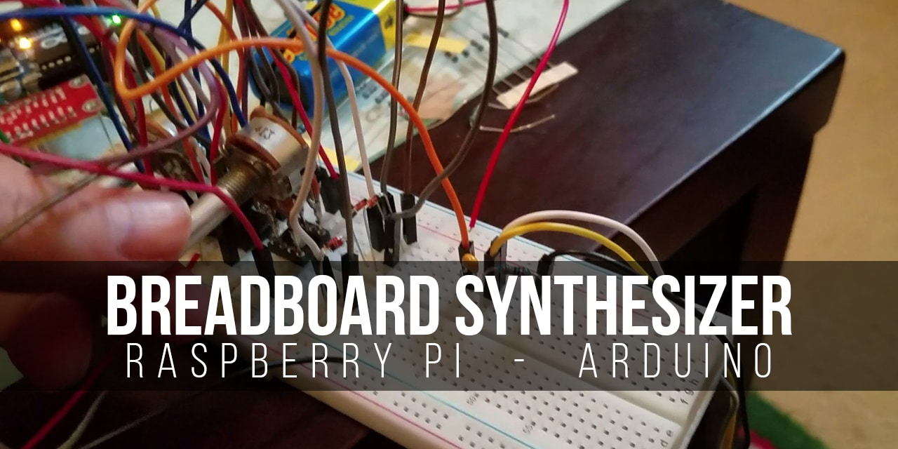
You don’t really need an amp, just a potentiometer and a knob. I’ll see if I can’t whip together a quick video for you on this. It’s really simple.
hi i cant seem to download your cabinet plans can you direct me to a link so i can .thanks
Frank – I don’t see where you’ve placed an order. Please use the Customer service link if I’m mistaken instead of commenting on this post.
What speakers do you use for this project?
All of that info is in the plan file.
Hi Mike,
Wich USB controllers do you use?
Do you have a connection plan for the wires?
The parts lists are in the plans. The instructions for wiring the controllers come with the controller kit.
🙂 Stupid question. 🙂
I see it now in the entire list.
Hi Mike, I am currently building the full size cabinet using your plan and things are coming along great. I purchased the Sanwa buttons but I see in this video you have graphics inside your player buttons. Where did you find the button inserts? Did you make them?
I made them using a Cricut vinyl cutter I got at a hobby store. I hope to do a video on that process at some point.
Hi Mike,
Thus looks really great. Been looking around for this and yours seems like the closest of what I been looking for. I may just have to change the arangements of buttons.
I would like to know before I make the purchase, what is the size of the monitor you use or the monitor sizes that could be use with your plans without changing the dimensions???
Thanks in advance.
Hey Mike,
Thanks for sharing your project and plans. Awesome.
Quick question about the Marquee. I highlight any big box can print these. Did you just have them print a banner on regular paper? Clearly a ton of options out on the web for printing, but just looking for what you chose to do.
Thanks,
Jason
I’ve done in a number of different ways. At the big box stores, just have them print it on glossy card stock. If you go to the web you can get a real nice vinyl print done which is cleaner, but a lot more expensive.
de lujo buen trabajo
What size screen did you use?
Is it posible for you to make one with the same “raspberry pi” and a “coin acceptor”?
Great Cabinet.
Yep. It works the same regardless of whether it is PC or Pi.
Hi Mike,
Great build! I’m 80% into mine as well, and i have a short question:
I also ordered 2 usb encoders for the 2 players, but on the retropie forums i noticed that many people mentioned that you need to modify a config file to tell the pie to accept 2 separate controllers.
Is this true? or did it just work for you plug n play?
If it needs to be done, can you please let me know your source for the steps?
Thanks
I did not have to change anything. Both worked just fine out of the box.
Awesome, thanks for the reply. They should arrive today and fingers crossed i hope they work without problems
what did you have to do to get the encoders to work with retropie? I built mine from the plans I order from you. I get the gamepad configured but pushing the buttons does nothing.
Hey Mike, The plans do not indicate the size of radius you use for the sides. How many inches did you set the centre point?
That’s not how compasses work. Watch the bartop arcade video.
Hi Mike,
Fantastic build and very nice instructions. My question is just wondering how well the Sanwa Arcade Joystick & Buttons and Easyget LED Arcade Controller has held up over extended use. When I read the reviews online I occasionally find one that talks about the buttons failing after a few weeks use but I don’t know if they just got a lemon or if there is a quality problem with the product.
Did the joystick and buttons hold up for you over time?
Thanks!
Al
No Al. I have not heard of such a thing. Sanwa is considered the gold standard for this stuff. I suspect they bought knock off parts. If the Louboutin shoes you bought off eBay for half price fell apart after two weeks you can probably guess they were fakes.
Glad to hear it they are working well. I looked at the bundle prior to see your build and thought they looked appealing over buying the controls separately (such as buying an i-pac + plus seperate buttons, etc.) as I am starting my first arcade cabinet build.
Awesome plans. I am in the final stages of building mine. Then I think I will donate it to Habitat for Humanity Restore and then build it again for fun. Thanks a lot Mike.
Hey Mike, what’s the approximate total cost to build one of these exactly how you’ve built it?
What size monitor is the bartop plans made for?
I was hoping to install a sheet of plexiglass over the monitor to protect it and give that arcade look. Any ideas tips on how to adjust your plans to account for that?
I will be making this tomorrow! Is it possible to keep this build to a single piece of plywood or mdf if I use a 26 inch monitor? thanks!
Hi Mike. Thanks for the video, guide and plans. Top job! Question – do you have any experience installing an on/off button in the cabinet for a safe/clean shutdown of the Pi? I’d be worried about causing corruption to the Pi/SD card if switching off at the mains after each use? Thank you
I just shut down the Pi using the Retropie menu before I power off. It takes about 3 seconds.
Best arcade and plans on the internet!! Thank you so much for this! Saved me some major headaches.
I bought your plans and built this. I have to say its the most fun I have had since I was a teenager! I am a pacman addict.
Mike- what length of T Molding do you recommend ordering for this project?
I am in the middle of building one of these based on your plan. I don’t really have a bar to install/store it on. I’m planning on a wall mount. Either shelve brackets or a French Cleat. I would prefer the cleat just worried about the location to mount it too on the cabinet. Would it good up with MDF?
Hi, brilliant tutorial. I have one question, which may be a stupid one but can you give details for the router bit you used for the t-molding?
See the arcade FAQs… but the short answer is, only your T-Molding manufacturer can answer that question.
https://www.thegeekpub.com/about-the-geek-pub/arcade-faqs/
Cheers!
Hi, just got your plans. Wondering about ‘how’ to print your drilling guides to ensure it comes out with the correct proportion, mainly the ‘Drilling Guide – 22 Buttons (2 Player)’. What paper size/printer settings?
I’d suggest reading the FAQs. 😉
https://www.thegeekpub.com/about-the-geek-pub/arcade-faqs/
4.5
Do you have Plans for same cabinet, but with 27 inch screen?
The Full Size plans use a 27″ screen. You could just chop the bottom off of it.
5
Hi Mike,
I’ve just bought your plans. I didn’t find if you had already answered this question before, but when I try to print in poster mode, the proportions still seem to be a bit too small and on big plans, the difference can be a problem.
I think that scaling might fix the problem, but before printing several tests to find the right scale %, I was wondering if there was a simpler way to do so.
Thanks in advance 🙂
I don’t usually answer questions in the comments (hardly ever read them), but I suspect this is your printer driver or printer not being perfectly aligned. I’ve never heard of this happening to anyone else (or me and I print all the time with poster mode).
Hi Mike,
Thanks for your anwer. I’m pretty sur it’s printer related indeed.
Have a nice day,
JG.