Blog
Arduino RGB LED Tutorial

Arduino RGB LED configuration! That’s what we’re covering in this tutorial! Most of the time you will be using LEDs that are a single color. Red, green, or blue for example. an RGB LED is basically three LEDs in one that can produce many thousands of colors!
Please note this tutorial is not about WS2812b or similar. We have a separate tutorial about those.
RGB LEDs Explained
Before we get into the Arduino RGB LED configuration, wiring, etc. Let’s first go over the basics of the RGB LED itself. The RGB LED consists of 3 LEDs in one. A red, a green, and a blue LED all in the same housing with separate leads for each. This allows the LED to mix colors at different intensities, allowing the presentation of many thousands of colors. There are 4-1 RGB LEDs that include a white LED. Though those are rarer, they work the same way.
RGB LED Pinout
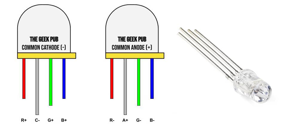
There are two type of RGB LEDs you will encounter and they are wired very differently
- Common Anode (+) – This type of LED has four pins. A cathode (-) for each color and a shared anode (+). The LED shares a common 3.3V to 5V input voltage. Grounding each anode will light the different colors.
- Common Cathode (-) – This type of LED has four pins. An anode (+) for each color and shared cathode (-). The LED shares a common ground, apply 3.3V to 5V to each Anode will light the different colors. This is the most common RGB LED.
Arduino RGB LED Colors
The human eye has only three cones (most people). These cones are detectors for red, green, and blue color. However, LEDs and LCDs are only capable of displaying those colors individually. These LEDs can be mixed to show show different intensities of these three colors. Because of the small size of each LED your eyes are tricked into seeing different colors that aren’t actually there!
With the Arduino and a technique called PWM, we can pulse each color of the LED separately to create many different colors. The PWM of the Arduino is programmable from 0-255. 0 would be off and 255 would be 100% brightness. That’s 256 possible variations. This gives us a total number of 16,777,216 possible colors to play with.
For example, On a common cathode LED, if we set PWM to these values we will get the color Magenta on our LED. Or at least that’s what your eye will be tricked into seeing!
- Red PWM = 255 (100%)
- Green PWM = 0 (0%)
- Blue PWM = 255 (100%)
Generally speaking, the red is always to the flat side of the LED and the longest pin is your common. However, any configuration is possible. If you don’t have the specs for your LED, you may just need to test it one pin at a time.
Arduino RGB LED Tutorial Video
Parts List for this Project
If you’d like to do this tutorial at home, here’s a handy parts list for the project. Some of these may be affiliate links. They cost you nothing, but pay us a small commission so that we can continue to create great content like this.
| QTY | PART/LINK | ||
|---|---|---|---|
| 1X | [icon name=”microchip” prefix=”fas”] | Arduino Uno | [icon name=”cart-plus” prefix=”fas”] |
| 1X | [icon name=”usb” prefix=”fab”] | USB Type B Cable | [icon name=”cart-plus” prefix=”fas”] |
| 1X | [icon name=”th” prefix=”fas”] | Solderless Breadboard | [icon name=”cart-plus” prefix=”fas”] |
| 1X | [icon name=”grip-lines” prefix=”fas”] | Jumper Wire Kit | [icon name=”cart-plus” prefix=”fas”] |
| 1X | [icon name=”ellipsis-h” prefix=”fas”] | Resistor Kit (220 Ohm) | [icon name=”cart-plus” prefix=”fas”] |
| 1X | [icon name=”lightbulb” prefix=”fas”] | LED Kit (incl RGB) | [icon name=”cart-plus” prefix=”fas”] |
Arduino RGB LED Wiring Diagram
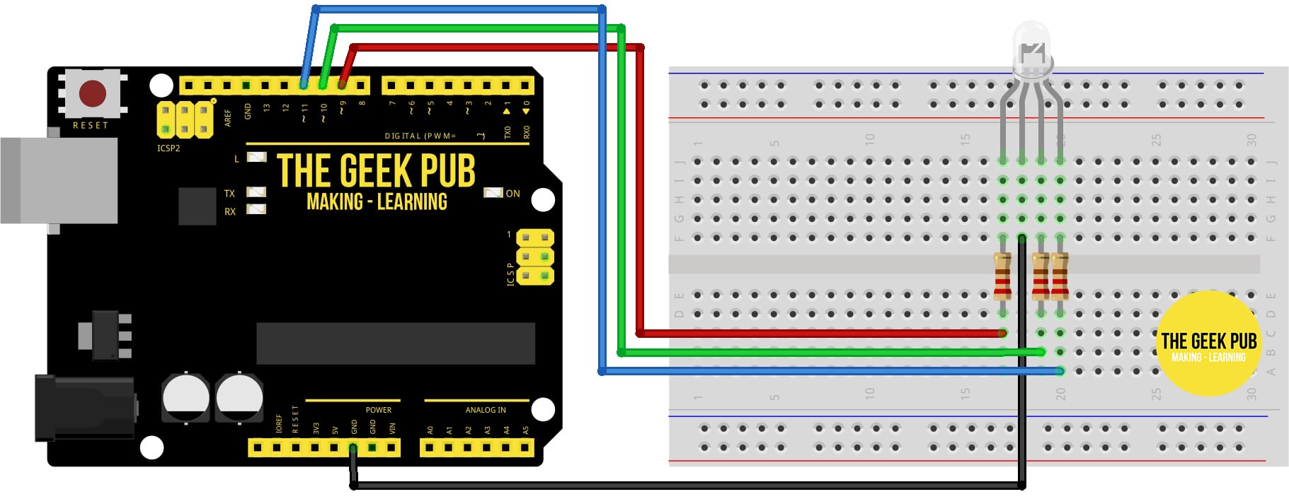
Since common cathode is by far the most common LED you will encounter, we’re going to use that in our Arduino RGB LED wiring diagram. Wire your RGB LED up as shown.
Note: If your colors seem off or do not appear correctly, it is most likely that your LED has a custom pinout. You may need to try applying power one pin at a time to determine which pin is which color. The common pin should always be the longest pin.
For this project it is important which pins we use. We need to use pins that have hardware PWM. These pins are identified with a tilde (~) next to them. If you don’t use PWM pins, this project will have problems. We’re going to use pins 9, 10, and 11.
- Arduino GND to LED Common Cathode (-)
- Arduino PIN 9 to Red LED Anode (+)
- Arduino PIN 10 to Green LED Anode (+)
- Arduino PIN 11 to Blue LED Anode (+)
Arduino RGB LED Code
This first set of code simply rotates through red, green, and then blue on the RBG LED waiting 500ms (half a second) between colors:
/*
    ARDUINO RGB LED TUTORIAL: Loop RGB
    By: TheGeekPub.com
    More Arduino Tutorials: https://www.thegeekpub.com/arduino-tutorials/
*/

const int PIN_RED   = 9; //Red LED on pin 9
const int PIN_GREEN = 10; //Green LED on pin 10
const int PIN_BLUE  = 11; //Blue LED on Pin 11

//variables to hold our color intensities
int red;
int green;
int blue;

/* This function "Set Color" will set the color of the LED
   rather than doing it over and over in the loop. */
void setColor(int R, int G, int B) {
  analogWrite(PIN_RED,   R);
  analogWrite(PIN_GREEN, G);
  analogWrite(PIN_BLUE,  B);
}

void setup() {
  //set all three pins to output mode
  pinMode(PIN_RED,   OUTPUT);
  pinMode(PIN_GREEN, OUTPUT);
  pinMode(PIN_BLUE,  OUTPUT);

}

void loop() {

  // set the colors of the LED
  // Loop through Red-Green-Blue and repeat
  setColor(255, 0, 0); //set LED to Red
  delay(500);
  setColor(0, 255, 0); //set LED to Green
  delay(500);
  setColor(0, 0, 255); //set LED to Blue
  delay(500);

}
You can see the LED will cycle through red, green, and blue.
But that’s kinda boring! Let’s ramp it up to the next level!
Arduino RGB Rainbow Code
This code will cycle through all of the 16 millions colors rapidly. If it’ too fast, you can increase the delay. This will create a very cool rainbow LED effect.
/*
    ARDUINO RGB LED TUTORIAL: RAINBOW COLOR
    By: TheGeekPub.com
    More Arduino Tutorials: https://www.thegeekpub.com/arduino-tutorials/
*/

const int PIN_RED   = 9; //Red LED on pin 9
const int PIN_GREEN = 10; //Green LED on pin 10
const int PIN_BLUE  = 11; //Blue LED on Pin 11

//variables to hold our color intensities and direction
//and define some initial "random" values to seed it
int red             = 254;
int green           = 1;
int blue            = 127;
int red_direction   = -1;
int green_direction = 1;
int blue_direction  = -1;

/* This function "Set Color" will set the color of the LED
   rather than doing it over and over in the loop above. */
void setColor(int R, int G, int B) {
  analogWrite(PIN_RED,   R);
  analogWrite(PIN_GREEN, G);
  analogWrite(PIN_BLUE,  B);
}

void setup() {
  //set all three pins to output mode
  pinMode(PIN_RED,   OUTPUT);
  pinMode(PIN_GREEN, OUTPUT);
  pinMode(PIN_BLUE,  OUTPUT);
}


void loop() {
  red = red + red_direction;   //changing values of LEDs
  green = green + green_direction;
  blue = blue + blue_direction;

  //now change direction for each color if it reaches 255
  if (red >= 255 || red <= 0)
  {
    red_direction = red_direction * -1;
  }
  if (green >= 255 || green <= 0)
  {
    green_direction = green_direction * -1;
  }
  if (blue >= 255 || blue <= 0)
  {
    blue_direction = blue_direction * -1;
  }
  setColor(red, green, blue);
  delay(5);    //a little delay is needed so you can see the change
}
Now you can see the real power of an RGB LED used in your project! An RGB LED is capable of thousands (or millions) of colors just by mixing the quantity of red, green, and blue using PWM.

Next Steps
Now that you’re an Arduino RGB LED expert, you can move on to the next tutorial or go back to the index!


how do i make it fade between colors?