Blog
Arduino Light Sensor Triggers an LED Tutorial
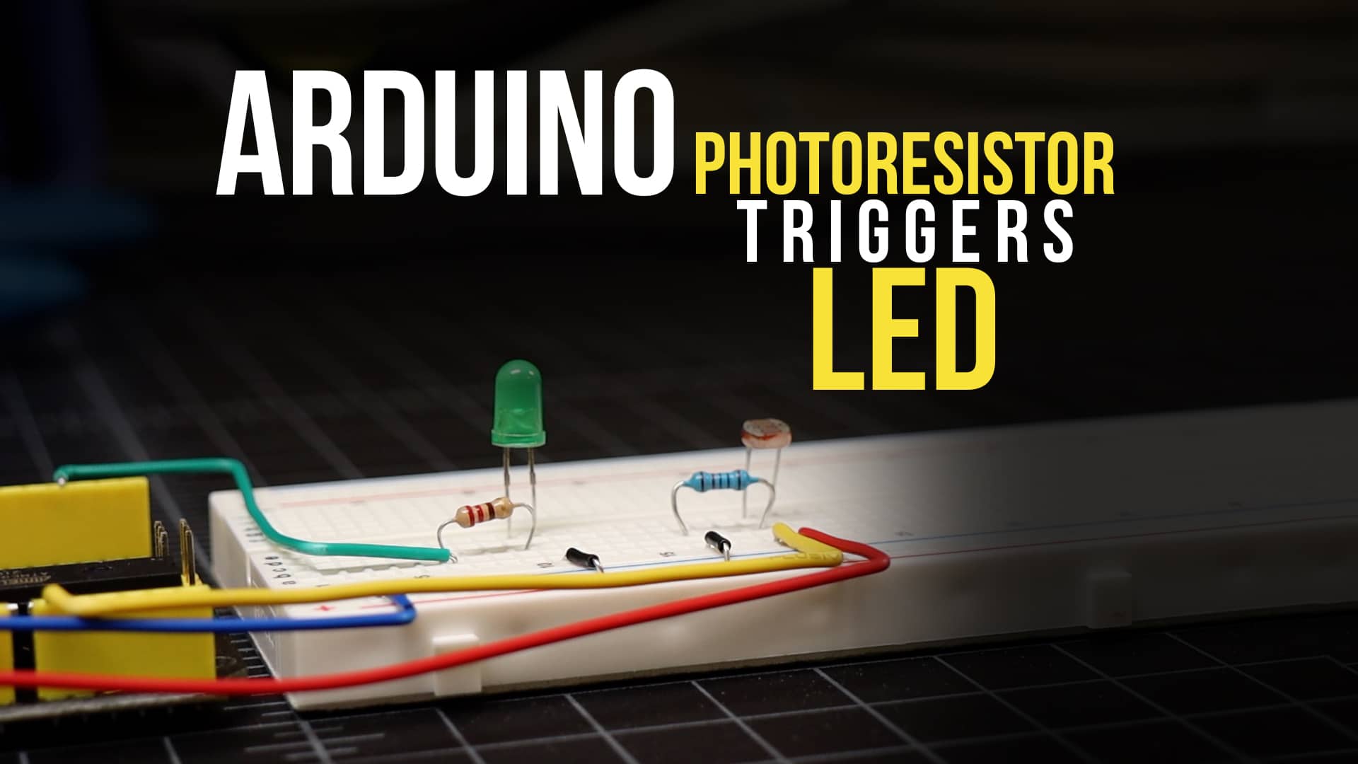
In this Arduino tutorial, we’re going to make a a circuit wherein a light sensor triggers and LED to light based on the the level of light in the room. Light sensors are actually light sensitive resistors (or photoresistors). With this type of resistor, its value resistance value changes based on the amount of light hitting the top of the sensors surface. The more light a light sensor receives, the lower its resistance value.
RELATED: Arduino Light Sensor Tutorial
Watch the Photoresistor Triggers LED Video
Parts List for this Tutorial
If you’d like to do this Arduino light sensor tutorial at home, here’s a handy parts list for the project. Some of these may be affiliate links. They cost you nothing, but pay us a small commission so that we can continue to create great content like this.
| QTY | PART/LINK | ||
|---|---|---|---|
| 1X | [icon name=”microchip” prefix=”fas”] | Arduino Uno | [icon name=”cart-plus” prefix=”fas”] |
| 1X | [icon name=”usb” prefix=”fab”] | USB Type B Cable | [icon name=”cart-plus” prefix=”fas”] |
| 1X | [icon name=”th” prefix=”fas”] | Solderless Breadboard | [icon name=”cart-plus” prefix=”fas”] |
| 1X | [icon name=”grip-lines” prefix=”fas”] | Jumper Wire Kit | [icon name=”cart-plus” prefix=”fas”] |
| 1X | [icon name=”lightbulb” prefix=”fas”] | Photoresistor Kit | [icon name=”cart-plus” prefix=”fas”] |
| 1X | [icon name=”ellipsis-h” prefix=”fas”] | Resistor Kit (220 & 10K Ohm) | [icon name=”cart-plus” prefix=”fas”] |
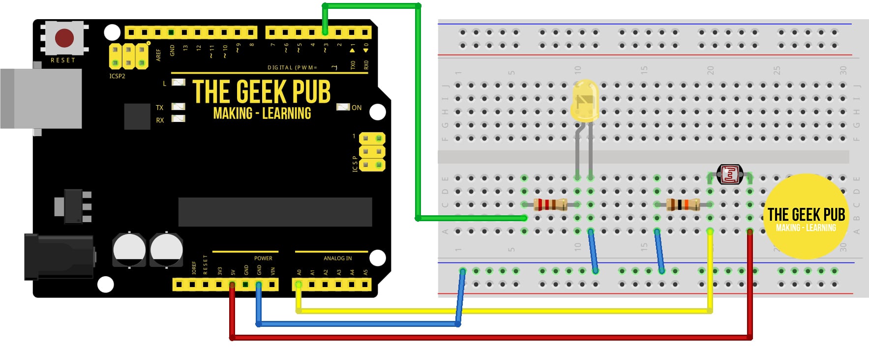
Wiring Diagram for Light Sensor Triggers and LED
Use the following wiring diagram to wire up your Arduino, LED and light sensitive resistor.
- Arduino PIN 3 to 220 Ohm Resistor
- 220 Ohm Resistor to LED Anode (+)
- LED Cathode (-) to GND
- Arduino PIN A0 to 10K Ohm Resistor and Photoresistor
- Photoresistor to Arduino 5V
- 10K Ohm Resistor to GND
Arduino Code for Light Sensor Triggers and LED
The more light the light sensor gets the lower its resistance value will become. This code checks that value and makes a decision when the reading passes a certain set of parameters. You can (and should) adjust these values based on your photoresistor’s specifications, or just to see what happens!
/*
    ARDUINO LIGHT SENSOR CONTROLS LED
    By: TheGeekPub.com
    More Arduino Tutorials: https://www.thegeekpub.com/arduino-tutorials/
*/

// constants won't change
const int LIGHT_SENSOR_PIN = A0; // Arduino pin connected to light sensor's  pin
const int LED_PIN          = 3;  // Arduino pin connected to LED's pin
const int ANALOG_THRESHOLD = 500;  // this sets the the threshold for when the LED turns on.

// variables will change:
int analogValue;

void setup() {
  pinMode(LED_PIN, OUTPUT); // set arduino pin to output mode
}

void loop() {
  analogValue = analogRead(LIGHT_SENSOR_PIN); // read the input on analog pin

  if(analogValue < ANALOG_THRESHOLD)
    digitalWrite(LED_PIN, HIGH); // turn on LED
  else
    digitalWrite(LED_PIN, LOW);  // turn off LED
}
Next Steps
Now you can move on to the next tutorial of go back the list!