Blog
Arduino Knight Rider LEDs (Cylon Eye)
In this tutorial, we’re going to show how to do the most awesome Arduino Knight Rider LEDs! It’s a highly requested article after our last update on blinking a single LED we sneak peaked this and apparently, everyone wants to know more!
For those who might not know, Knight Rider is a TV show from the 1980’s staring David Hasselhoff and featured a futuristic Pontiac Trans-Am called KITT. KITT was a fully autonomous car that seamed to be self aware and offered all kinds of features and assistance to his owner Micheal Knight, who worked for a covert operation fighting crime. One of the signature designs of this car was the flashing LED array across the front of the car. This flashing LED array is also a signature feature of the Cylon’s eyes from Battlestar Galactica.


Creating the Arduino Knight Rider LEDs
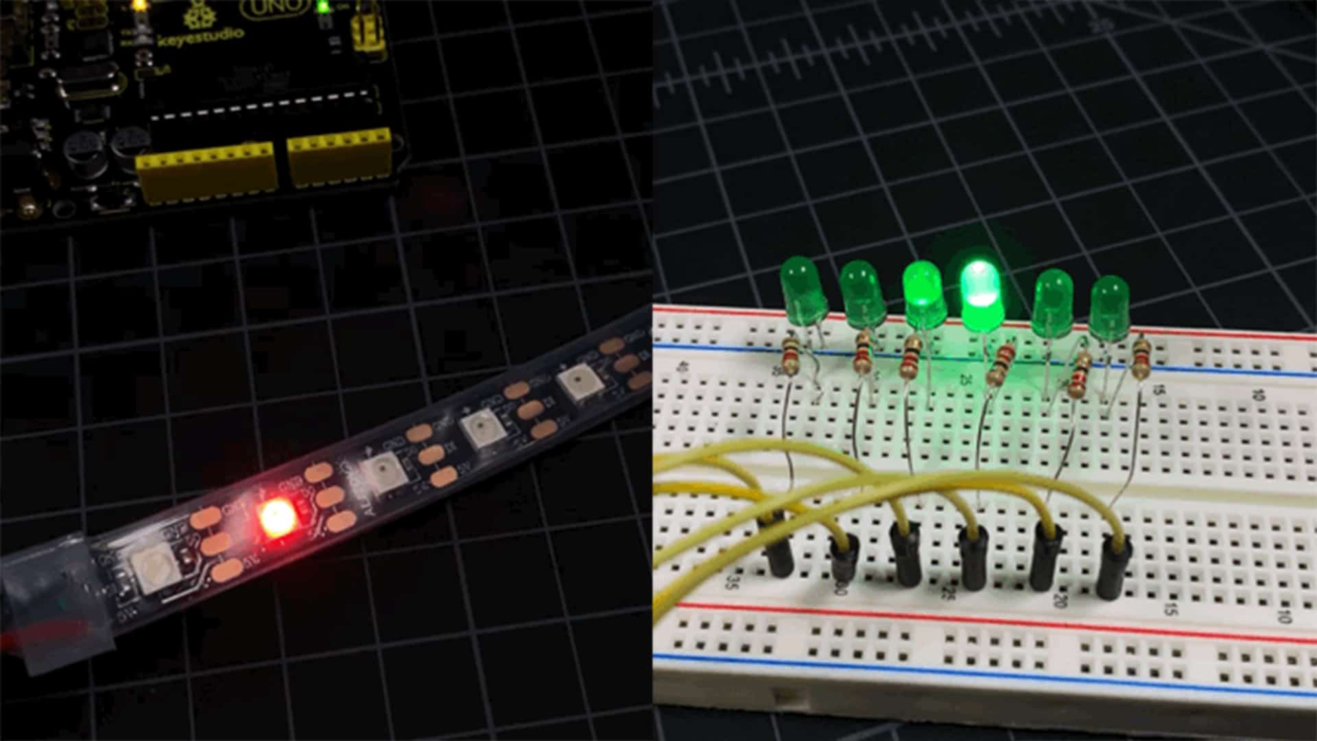
There are two different ways to create the Arduino Knight Rider LEDs. The first is with standard LEDs, and the second is using a set of WS2812b addressable LEDs. We’ll go over both options!
OPTION 1: Knight Rider LED with Standard LEDs
Using standard LEDs, you can use as many LEDs as you have digital I/O pins on your Arduino. Each LED will be connected to a dedicated digital I/O pin to power it. If you’re looking to do more than that, check out option 2 below where you can run an unlimited amount with just a single pin!
We will need to attach a 220 Ohm resistor in series with each LED for limiting current. In our example we’re only going to use 6 LEDs for simplicity sake. So to get started, the first thing you’ll need to do is wire up the hardware of the Arduino to connect all of the LEDs. I am using green LEDs, but you can most certainly use red (or any other color you like).
Parts List for Option 1
Here’s a handy parts list for building the Arduino Knight Rider LEDs using just LEDs
| QTY | PART / LINK | ||
|---|---|---|---|
| 1X | [icon name=”microchip” prefix=”fas”] | Arduino Uno | [icon name=”cart-plus” prefix=”fas”] |
| 1X | [icon name=”usb” prefix=”fab”] | USB Type B Cable | [icon name=”cart-plus” prefix=”fas”] |
| 1X | [icon name=”ellipsis-h” prefix=”fas”] | Resistor Kit (220 Ohm) | [icon name=”cart-plus” prefix=”fas”] |
| 1X | [icon name=”lightbulb” prefix=”fas”] | LED Kit | [icon name=”cart-plus” prefix=”fas”] |
| 1X | [icon name=”th” prefix=”fas”] | Solderless Breadboard | [icon name=”cart-plus” prefix=”fas”] |
| 1X | [icon name=”grip-lines” prefix=”fas”] | Jumper Wire Kit | [icon name=”cart-plus” prefix=”fas”] |
Some of these links are affiliates. If you use them it costs you nothing, but we get a small commissions and that helps us keep making content for you!
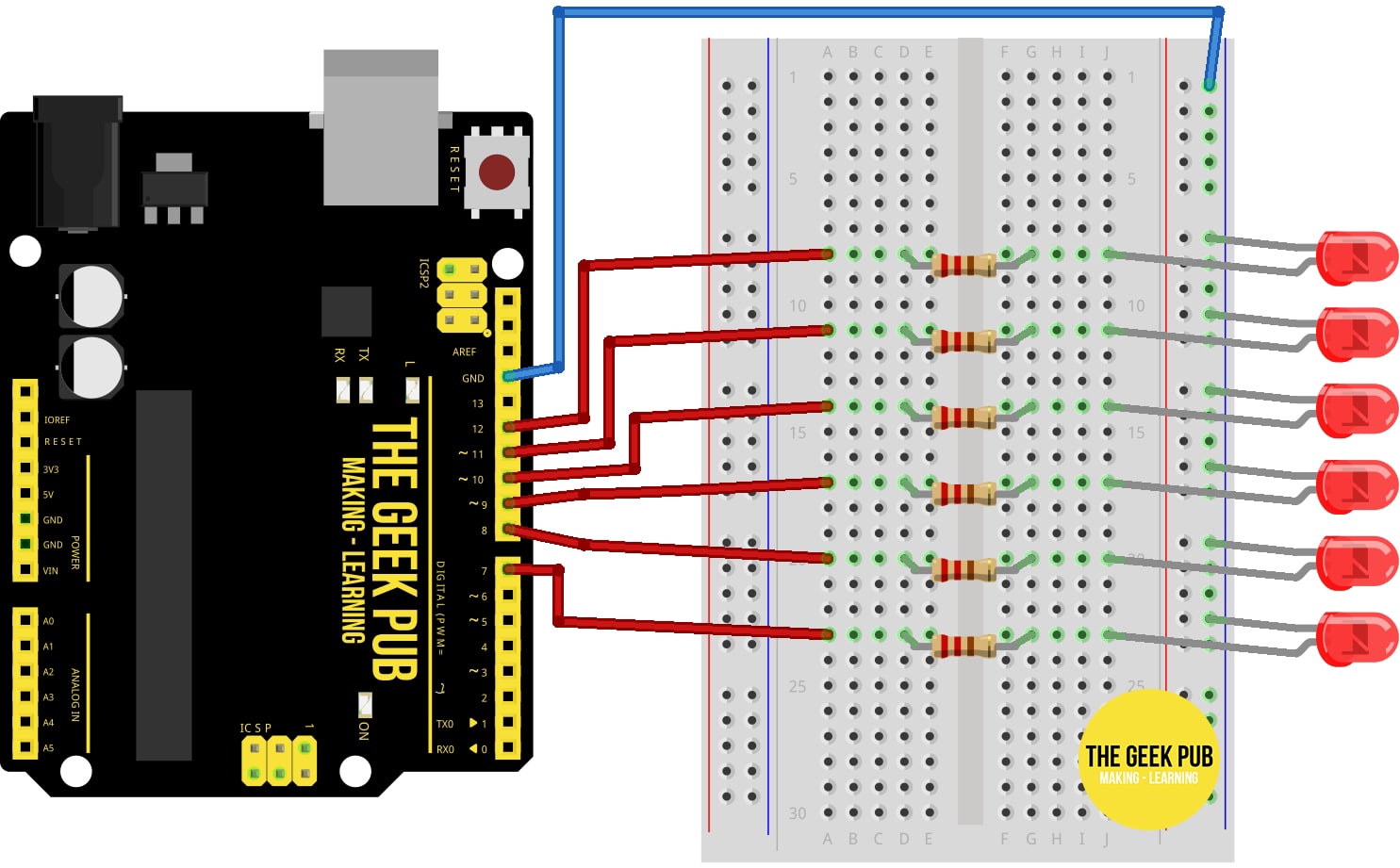
Use the following wiring diagram to wire up the Knight Rider LEDs:
- Arduino GND to breadboard GND
- All LED cathode to breadboard GND
- Arduino PIN 12 to 220 Ohm resistor to LED anode
- Arduino PIN 11 to 220 Ohm resistor to LED anode
- Arduino PIN 10 to 220 Ohm resistor to LED anode
- Arduino PIN 9 to 220 Ohm resistor to LED anode
- Arduino PIN 8 to 220 Ohm resistor to LED anode
- Arduino PIN 7 to 220 Ohm resistor to LED anode
After you get the hardware wired up you’ll need to drop the following code into the Arduino IDE and upload it. If you use more or less LEDs (or diffent pins) just be sure to change the pins in pinArray.
int pinArray[] = {12, 11, 10, 9, 8, 7};
int count = 0;
int timer = 10;

void setup(){
  for (count=0;count<6;count++) {
    pinMode(pinArray[count], OUTPUT);
  }
}

void loop() {
  for (count=0;count<5;count++) { digitalWrite(pinArray[count], HIGH); delay(timer); digitalWrite(pinArray[count + 1], HIGH); delay(timer); digitalWrite(pinArray[count], LOW); delay(timer*2); } for (count=5;count>0;count--) {
      digitalWrite(pinArray[count], HIGH);
      delay(timer);
      digitalWrite(pinArray[count - 1], HIGH);
      delay(timer);
      digitalWrite(pinArray[count], LOW);
      delay(timer*2);
    }
}
OPTION 2: Knight Rider LED with WS2812b LEDs
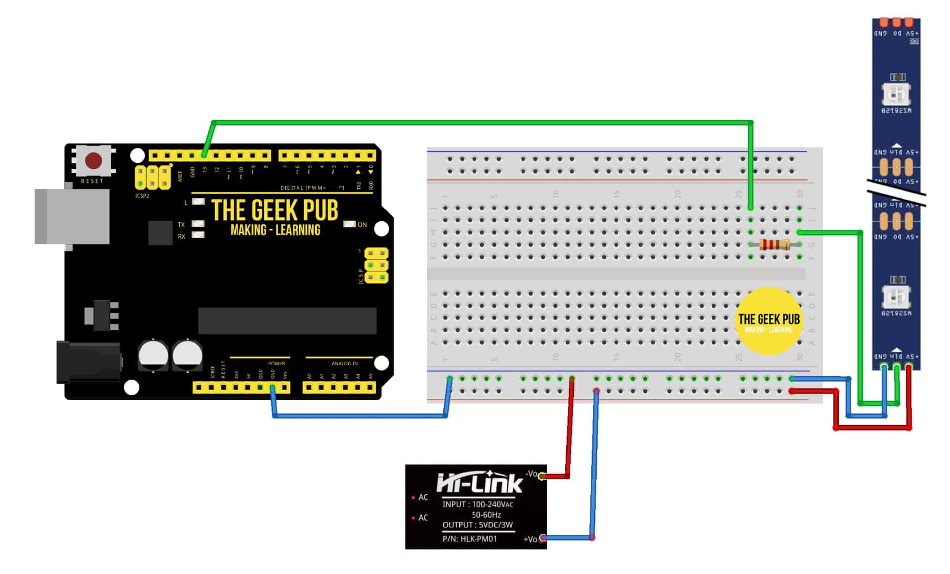
The second option for doing Arduino Knight Rider LEDs is to use a strip of addressable WS2812b LEDs. These are awesome because you can run a basically unlimited number of LEDs from a single pin. WS2812b LEDs contain a small integrated circuit at each LED that allows the Arduino to send a command over the data line to each LED individually. In fact, without receiving a command, all LEDs stay in the off position, even when power is applied to the Vcc+ pins.
In the wiring diagram below you’ll notice that we’re adding an external power supply. If you’re only going to run 8 or less LEDs, you can skip the power supply and connect these directly to the Arduino’s 5V pin. For more than 8 LEDs you will need an external power supply for the LED strip.
Parts List for Option 2
Here’s a handy parts list for building the Arduino Knight Rider LEDs using a WS2812b LED strip:
| QTY | PART / LINK | ||
|---|---|---|---|
| 1X | [icon name=”microchip” prefix=”fas”] | Arduino Uno | [icon name=”cart-plus” prefix=”fas”] |
| 1X | [icon name=”usb” prefix=”fab”] | USB Type B Cable | [icon name=”cart-plus” prefix=”fas”] |
| 1X | [icon name=”th” prefix=”fas”] | Solderless Breadboard | [icon name=”cart-plus” prefix=”fas”] |
| 1X | [icon name=”grip-lines” prefix=”fas”] | Jumper Wire Kit | [icon name=”cart-plus” prefix=”fas”] |
| 1X | [icon name=”lightbulb” prefix=”fas”] | WS2812b LED Strip | [icon name=”cart-plus” prefix=”fas”] |
| 1X | [icon name=”plug” prefix=”fas”] | 5V Power Supply (for WS2812b LED Strips) | [icon name=”cart-plus” prefix=”fas”] |
To wire up the WS2812b Arduino Knight Rider LEDs, use the following wiring diagram:
- PIN 11 to 330 Ohm resistor to WS2812b DATA IN
- Arduino GND to Breadboard GND
- 5V Power Supply GND to Breadboard GND
- 5V Power Supply Vcc+ to WS2812b Vcc+
- WS2812b GND to Breadboard GND
Next up we’ll need to put the following lines of code into the Arduino IDE and upload them. In the interest of learning this is a very simple code. However, we highly recommend you look at the Peter Gullberg’s codePeter Gullberg’s code. He;s created a fantastic fading algorithm to make the most authentic Knight Rider strip we’ve seen. However the complexities are outside of this basic tutorial.
#include <Adafruit_NeoPixel.h>
int PIN = 11;
int count = 0;
int timer = 10;

Adafruit_NeoPixel strip = Adafruit_NeoPixel(6, PIN, NEO_GRB + NEO_KHZ800); //defines the strips properties

void setColor(int Pixel, int R2, int G2, int B2) {
  uint32_t color = strip.Color(R2, G2, B2); // make a color
  strip.setPixelColor(Pixel, color); //set a single pixel color
  strip.show(); //update the colors
}
void setup() {
  strip.begin(); // initialize the WS2812b strip
  strip.show(); // just make sure everything is off
}

void loop() {
  for (count = 0; count < 5; count++) { setColor(count, 255, 0, 0); delay(timer); setColor(count + 1, 255, 0, 0); delay(timer); setColor(count, 0, 0, 0); delay(timer * 2); } for (count = 5; count > 0; count--) {
    setColor(count, 255, 0, 0);
    delay(timer);
    setColor(count - 1, 255, 0, 0);
    delay(timer);
    setColor(count, 0, 0, 0);
    delay(timer * 2);
  }
}
Be sure to change the COUNT constant in your code to set the amount of LEDs you’re using.
I encourage you to play around with this code and you can come up with some really neat variations. Here’s a 15 pixel version in blue:
We hope this helps you with your Knight Rider (or Cylon eye) Arduino project. If you run into any problems, leave a comment below and we will try to help you out!
Next Steps
From here you can learn more about the Arduino using the following links:


5
This is totally going on the front of my car! Woo Woo
On your car? I am putting this on my new gaming PC!
For those of you trying to figure out which is the positive leg (Anode) and negative leg (Cathode) of the LED. The longer leg is the positive (+) leg.
The Neopixel version would also work on my 8 led Ring correct, with just a little code modification ?
Great idea. I am new to Arduino. Is there a place to get a good one like this premade? Would like to put one in my PC, but so far the ones you can buy that I have found are only 8 or 10 LEDs. That does not look too good in a 5 1/4 bay.
1
0.5
1.5
For some reason it will only use 6 LEDs regardless of what I put in for count, thoughts?
FOUND MY ANSWER, THANKS!!