Blog
Arduino Light Sensor Tutorial
In this Arduino light sensor tutorial we’re going to show the basics of connecting a light sensor (or photoresistor) to the Arduino and reading its input. A photoresistor is a sensor that changes resistance based on the amount of light being delivered to its sensor. In this way we not only detect whether it is light or dark, but we can also detect with some degree of accuracy how bright (or how dark) the ambient environment is.
RELATED: List of Arduino Sensors
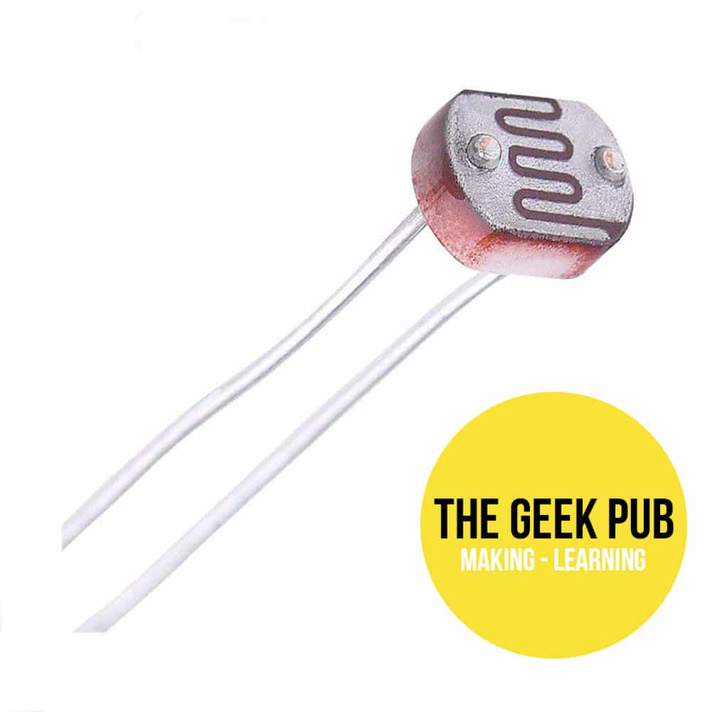
A photoresistor at its core is nothing more than a variable resistor. A variable resistor than changes resistance based on light levels it detects. A photoresistor has two leads, just like a normal resistor and it can pass current in either direction. Photoresistors are not polarized (they do not have a positive or negative lead). It can be connected in the circuit either direction with no change to its operation or performance.
A photoresistor works by decreasing its resistance as the ambient light increases. In other words, the brighter the light the less resistance!
Parts List for this Project
If you’d like to do this Arduino light sensor tutorial at home, here’s a handy parts list for the project. Some of these may be affiliate links. They cost you nothing, but pay us a small commission so that we can continue to create great content like this.
| QTY | PART/LINK | ||
|---|---|---|---|
| 1X | [icon name=”microchip” prefix=”fas”] | Arduino Uno | [icon name=”cart-plus” prefix=”fas”] |
| 1X | [icon name=”usb” prefix=”fab”] | USB Type B Cable | [icon name=”cart-plus” prefix=”fas”] |
| 1X | [icon name=”th” prefix=”fas”] | Solderless Breadboard | [icon name=”cart-plus” prefix=”fas”] |
| 1X | [icon name=”grip-lines” prefix=”fas”] | Jumper Wire Kit | [icon name=”cart-plus” prefix=”fas”] |
| 1X | [icon name=”lightbulb” prefix=”fas”] | Photoresistor Kit | [icon name=”cart-plus” prefix=”fas”] |
| 1X | [icon name=”ellipsis-h” prefix=”fas”] | Resistor Kit (220 Ohm) | [icon name=”cart-plus” prefix=”fas”] |
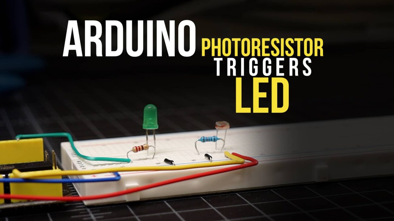
Wiring a Photoresistor to the Arduino
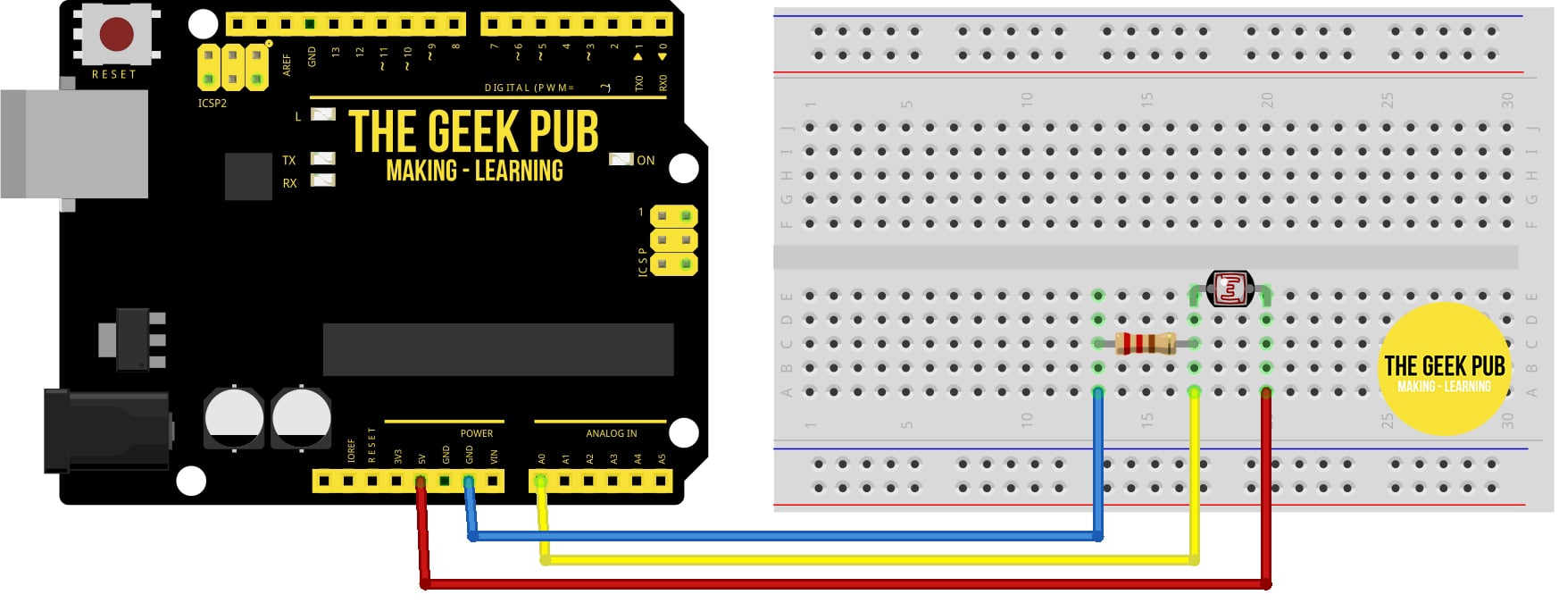
Wiring up the photoresistor as part of our Arduino light sensor tutorial is very easy. However, in order to get accurate readings, we do will need to add an pull down resistor to the circuit. We’ll go deeper into why that’s necessary in a future tutorial.
In order to measure the resistance of the photoresistor, we will need to connect to one of the analog pins. The analog pins are A0-A5 on the Uno. In this tutorial , we’re going to use PIN A0.
- Arduino PIN A0 to Photoresistor PIN 1
- Resistor PIN 1 to Photoresistor PIN 1
- Resistor PIN 2 to Arduino 5V
- Arduino GND to Photoresistor PIN 2
Arduino Sketch for Reading a Photoresistor
This code reads the resistance and then displays the value on the screen along with our interpretation of the reading (“dark” to “bright”). Please note that your particular brand and spec of photoresistor may have different resistance levels and you may need to adjust the numbers accordingly.
void setup() {
  // initialize serial communication at 9600 bits per second:
  Serial.begin(9600);
}

void loop() {
  // reads the input on analog pin A0 (value between 0 and 1023)
  int prValue = analogRead(A0);

  Serial.print("Resistance reading = ");
  Serial.print(prValue);   // the raw analog reading

  // We'll have a few threshholds, qualitatively determined
  if (prValue < 10) {
    Serial.println(" - Dark");
  } else if (prValue < 200) {
    Serial.println(" - Dim");
  } else if (prValue < 500) {
    Serial.println(" - Light");
  } else if (prValue < 800) {
    Serial.println(" - Bright");
  } else {
    Serial.println(" - Very bright");
  }

  delay(500);
}
Next Steps
From here you can move on to the next project or go back to the index!