Blog
Arduino Traffic Light Project
One of the very first projects almost all people do when they get an Arduino is to make the traffic light project. It’s an incredibly simple project but it teaches you some of the most relevant fundamentals of the Arduino. We’re going to make the Arduino traffic light project in this tutorial, step by step in a simple to understand way that you can even do with your kids. It’s a great way to introduce them to electronics, programming, and micro-controllers.
Parts list for this Project
| QTY | PART/LINK | ||
|---|---|---|---|
| 1X | [icon name=”microchip” prefix=”fas”] | Arduino Uno | [icon name=”cart-plus” prefix=”fas”] |
| 1X | [icon name=”usb” prefix=”fab”] | USB Type B Cable | [icon name=”cart-plus” prefix=”fas”] |
| 1X | [icon name=”th” prefix=”fas”] | Solderless Breadboard | [icon name=”cart-plus” prefix=”fas”] |
| 1X | [icon name=”grip-lines” prefix=”fas”] | Jumper Wire Kit | [icon name=”cart-plus” prefix=”fas”] |
| 1X | [icon name=”lightbulb” prefix=”fas”] | LED Kit | [icon name=”cart-plus” prefix=”fas”] |
| 1X | [icon name=”ellipsis-h” prefix=”fas”] | Resistor Kit (220 Ohm) | [icon name=”cart-plus” prefix=”fas”] |
Some of these links are affiliates. If you use them it costs you nothing, but we get a small commissions and that helps us keep making content for you!
If you need to order parts for this project, here’s a simple list to get you started!
Arduino Traffic Light Wiring
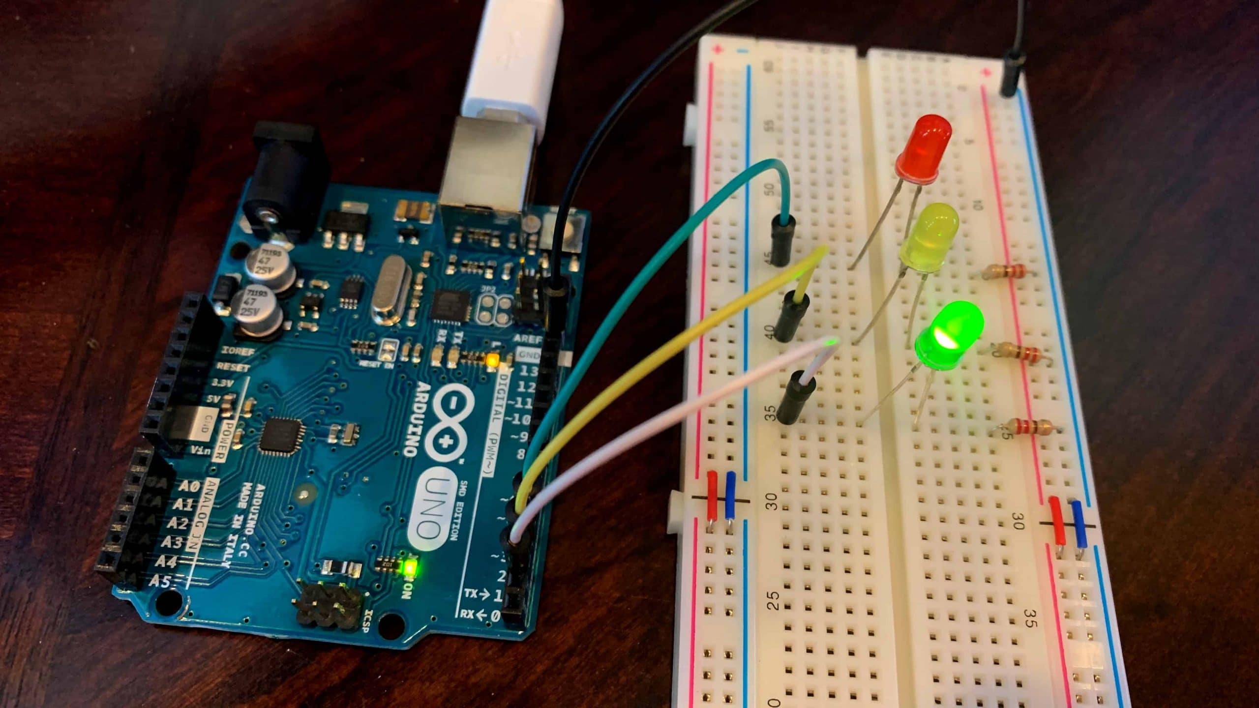
The wiring of the Arduino traffic light project is beyond simple. It’s partly what makes it one of those great educational projects. Each LED will connect to a dedicated pin on the Arduino and share a common ground. We’ll use 100 ohm resistors to prevent a current overload on the LEDs.
- PIN 2 to Green LED + (anode)
- PIN 3 to Yellow LED + (anode)
- PIN 4 to Red LED + (anode)
- GND to common ground on breadboard
- Place a 100 ohm resistor between each LED – (cathode) and the common ground rail on the breadboard
I’ve illustrated it for you here in this Fritzing diagram. Make sure the resistor is on the negative (cathode) lead. The negative (-) or cathode lead of the LED will be a shorter lead. While the anode (or +) lead will be longer. Failure to use a 100 ohm resistor will cause your LEDs to burn out quickly. If you don’t have any 100 ohm LEDs you could substitute something close, such as a 150 ohm resistor.
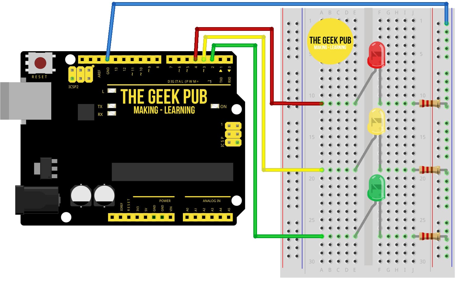
Nothing will happen with these LEDs until we write some code to control them. So let’s move on and do that next!
Arduino Traffic Light Code
So it is not time to write a basic Arduino program to control these LEDs in a traffic light pattern. This code is very simple and should be easy to understand for most. If you’re having trouble “getting it”, there are some great tutorials on the Arduino website.
Traffic Light Variables
The first thing we’re going to do is create some variables. We could skip this part, but then we’d have to make the same change in numerous places to change the timing and configuration of our traffic lights. We might want to make the red light longer or shorter for example, and all we will need to do is change DELAY_RED variable and re-upload the code to the Arduino. A change that takes just a second or two.
The main two variable will be for DELAY and for LED pin location on the Arduino for the corresponding color of LED. This will also make our program a little easier to understand. Since we made the pin assignments above in the Arduino traffic light wiring, we now need to tell the code where everything is connected.
// variables
int GREEN = 2;
int YELLOW = 3;
int RED = 4;
int DELAY_GREEN = 5000;
int DELAY_YELLOW = 2000;
int DELAY_RED = 5000;
Traffic Light Pin Assignments
Now that we’ve created our variables, we need to tell the Arduino how to assign those pins. In our case these pins will be output pins so that we can send 3.3v to each LED. To do this we will use the pinMode function. The pinMode function accepts two parameters: pin number and mode. Mode will either be input or output. Our pin setup code looks like this:
// basic functions
void setup()
  {
  pinMode(GREEN, OUTPUT);
  pinMode(YELLOW, OUTPUT);
  pinMode(RED, OUTPUT);
  }
Traffic Light Loop Function
The Loop function is exactly like what is sounds. It will loop through our other functions over and over. We’re going to call our own functions inside the loop function to change our LED in a traffic light pattern.
void loop()
  {
  green_light();
  delay(DELAY_GREEN);
  yellow_light();
  delay(DELAY_YELLOW);
  red_light();
  delay(DELAY_RED);
  }
Traffic Light Update Functions
These functions do exactly what you might think. They turn on the LED of our color choice, and turn off any other LEDs that are currently on.
void green_light()
  {
  digitalWrite(GREEN, HIGH);
  digitalWrite(YELLOW, LOW);
  digitalWrite(RED, LOW);
  }

void yellow_light()
  {
  digitalWrite(GREEN, LOW);
  digitalWrite(YELLOW, HIGH);
  digitalWrite(RED, LOW);
  }

void red_light()
  {
  digitalWrite(GREEN, LOW);
  digitalWrite(YELLOW, LOW);
  digitalWrite(RED, HIGH);
  }
Compile and Upload the Traffic Light Code
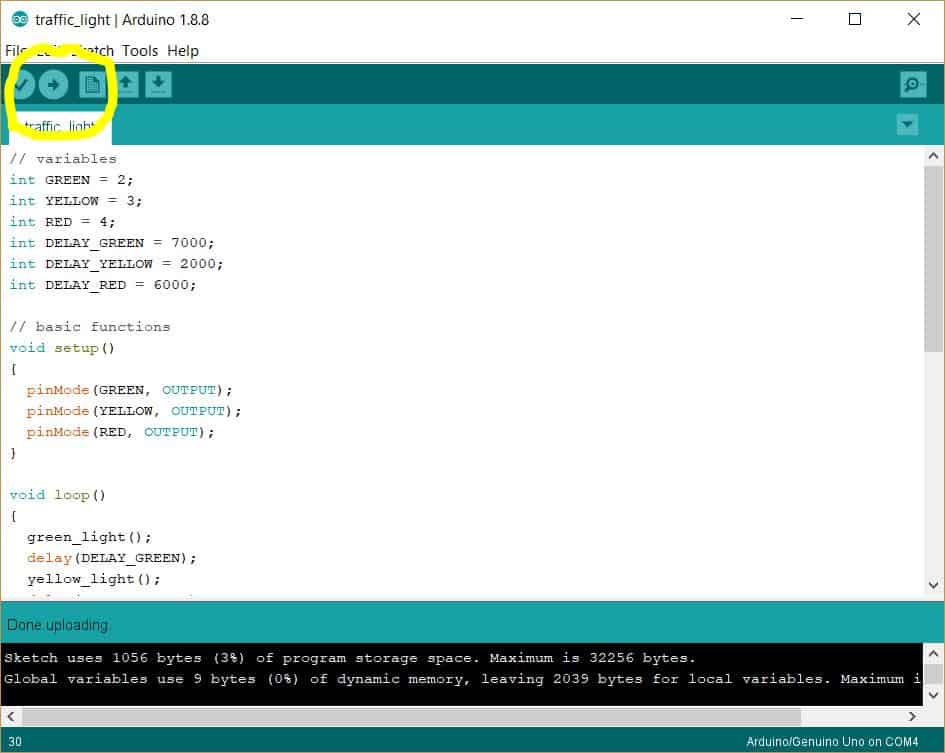
Now that we have all of our code in place it is time to upload it to the Arduino Uno. Click the verify button in Sketch and make sure your code verifies, if it doesn’t check for typos.
With your Arduino plugged into your PC via USB, click the upload icon in Arduino Sketch. Your code should start executing within a second or two and your traffic lights should start working.
Learning More about the Arduino Traffic Light Project
Now that you’ve completed the Arduino traffic light project, take some time to go over the code again and make some changes. Try changing the DELAY_RED, DELAY_GREEN, and DELAY_YELLOW variables to longer of shorter intervals. The integer is in milliseconds, so each second is represented by increments of 1000. Some US cities with red light cameras have made their yellow lights shorter in order to give more tickets. Don’t be evil like that that!
RELATED PROJECT: Arduino Train Crossing Project
If you have any ideas or comments on your traffic light project, leave them below!
Complete Code for Traffic Light Project
If you just want the complete traffic light project code, copy and paste the following into Sketch and upload it to your Arduino.
// variables
int GREEN = 2;
int YELLOW = 3;
int RED = 4;
int DELAY_GREEN = 5000;
int DELAY_YELLOW = 2000;
int DELAY_RED = 5000;

// basic functions
void setup()
  {
  pinMode(GREEN, OUTPUT);
  pinMode(YELLOW, OUTPUT);
  pinMode(RED, OUTPUT);
  }

void loop()
  {
  green_light();
  delay(DELAY_GREEN);
  yellow_light();
  delay(DELAY_YELLOW);
  red_light();
  delay(DELAY_RED);
  }

void green_light()
  {
  digitalWrite(GREEN, HIGH);
  digitalWrite(YELLOW, LOW);
  digitalWrite(RED, LOW);
  }

void yellow_light()
  {
  digitalWrite(GREEN, LOW);
  digitalWrite(YELLOW, HIGH);
  digitalWrite(RED, LOW);
  }

void red_light()
  {
  digitalWrite(GREEN, LOW);
  digitalWrite(YELLOW, LOW);
  digitalWrite(RED, HIGH);
  }
Next Steps
Now that you’ve finished the Arduino Traffic Light Tutorial, you can move on to the next tutorial or go back to main index.


0.5