Blog
How to Setup a Keypad on an Arduino
In this basic tutorial we will learn how to setup a keypad on an Arduino. Keypads can be used to control access to things, such as unlocking a door or a safe. Keypads can be added to a myriad of Arduino projects, for learning, or for real world projects. In addition to controlling access to things, these keypads can also be used as simple input devices to control other things. Bob at I Like To Make Stuff even used his Arduino Keypads to automate blast gates in his wood shop. The uses are almost infinite!
First thing we will do is explain how keypads work. Their simplicity might surprise you! Then we’ll walk through setting up a passcode on the Arduino that will print out numbers on the serial console as we type them on the keypad. Finally, we’ll setup an LED that will turn green when successfully enter the passcode. If you want to expand on this you could replace the LED with a relay to make this project unlock a door. Let us know in the comments what you do with your setup!
Parts List for this Project
If you’re just getting started or just want a simple list of parts, we’ve provided a simple shopping list for you. Some of these may be affiliate links. If you use them it costs you nothing. We may get a small commission that helps us keep making awesome content like this!
| QTY | PART/LINK | ||
|---|---|---|---|
| 1X | [icon name=”microchip” prefix=”fas”] | Arduino Uno | [icon name=”cart-plus” prefix=”fas”] |
| 1X | [icon name=”usb” prefix=”fab”] | USB Type B Cable | [icon name=”cart-plus” prefix=”fas”] |
| 1X | [icon name=”th” prefix=”fas”] | Solderless Breadboard | [icon name=”cart-plus” prefix=”fas”] |
| 1X | [icon name=”grip-lines” prefix=”fas”] | Jumper Wire Kit | [icon name=”cart-plus” prefix=”fas”] |
| 1X | [icon name=”ellipsis-h” prefix=”fas”] | Potentiometer Kit | [icon name=”cart-plus” prefix=”fas”] |
| 1X | [icon name=”lightbulb” prefix=”fas”] | LED Kit | [icon name=”cart-plus” prefix=”fas”] |
| 1X | [icon name=”tv” prefix=”fas”] | 16×2 LCD Character Display | [icon name=”cart-plus” prefix=”fas”] |
| 1X | [icon name=”keyboard” prefix=”fas”] | Keypad for Arduino | [icon name=”cart-plus” prefix=”fas”] |
RELATED: Our Picks for the Best Arduino Starter Kits
How Keypads Work
Before we go into the process of putting our project together, let’s quickly discover how the Keypads themselves work. As I mentioned previously, they are quite simplistic in design and operation.
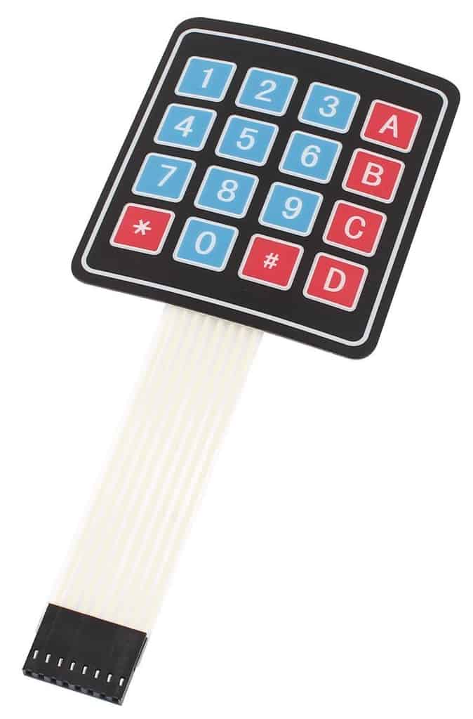
In this article, we’ll be using a 4×4 membrane keypad. These membrane keypads come in all kinds of shapes and sizes. If you already have one in a different size, it should be quite simple to modify the code below for your keypad. Membrane keypads work just like any other keypad, with the enhanced benefit that they are incredibly thin. They’re probably not the best for industrial applications however, as they may not last as long as keypads with mechanical switches. Regardless of design or construction, most of these keypads operate on the exact same principles.
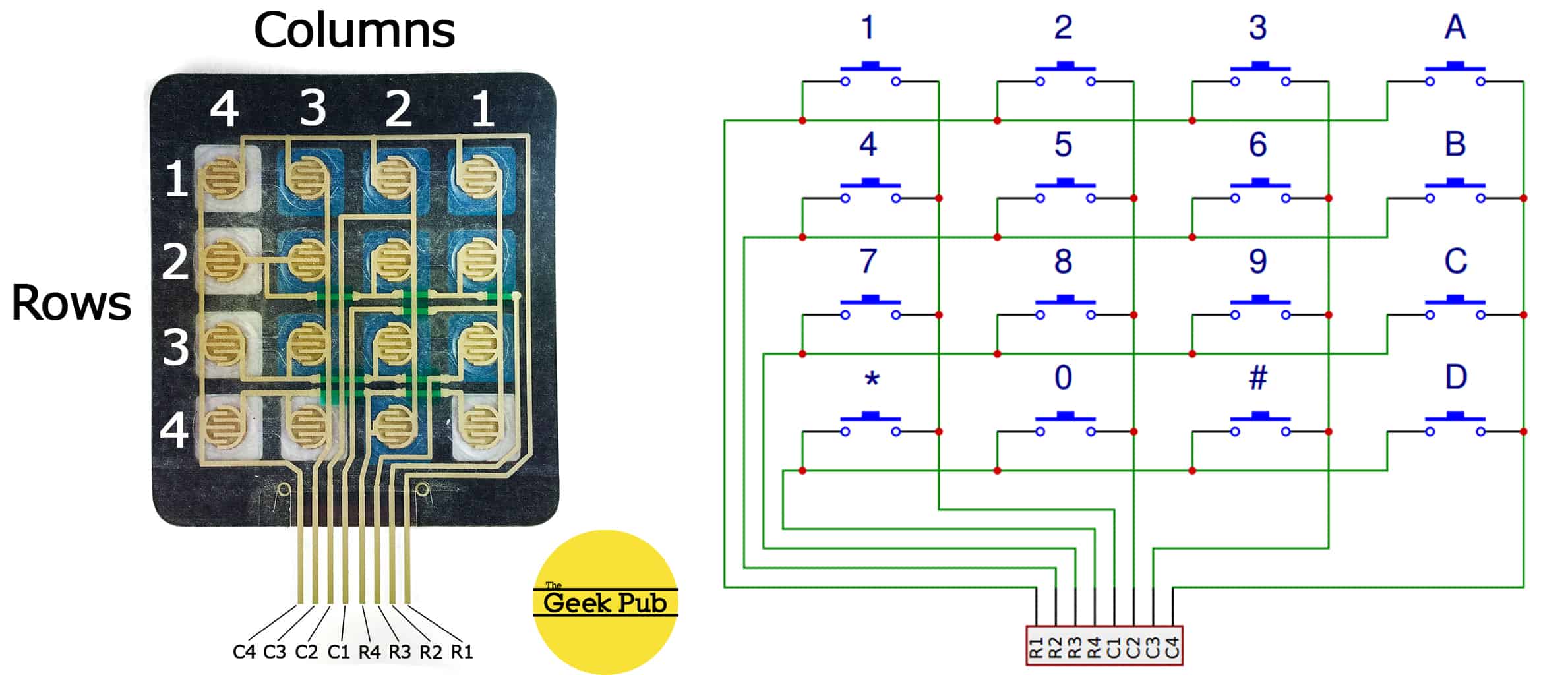
On the underside of each key in a membrane keypad is a membrane switch (hence the name). In each row of the membrane is a horizontal trace that connects every membrane switch together. In every column is a vertical trace that also connects each switch together. With four rows and four columns, this allows 16 keys to be read with only 8 pins. When a key is pressed down it causes the trace on one row and one column to make electrical contact.
In the diagram below on the right, we’ve illustrated this concept with an electrical diagram. On the right, we’ve removed the backing from membrane switch so that you can see how the traces are physically laid out. Other matrix keypads such as 3×4, 4×6, and 8×8 are all designed in this exact same manner. They will simply have more or less pins.
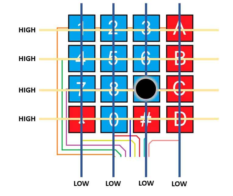
To determine which button is pressed the Arduino detects a connection at a certain row and column within the matrix. Let’s walk through the four operations that make this possible.
Step 1 – At idle, when none of the membrane keypad’s switches are being pressed, all of the rows are held low and all of the columns are held high.
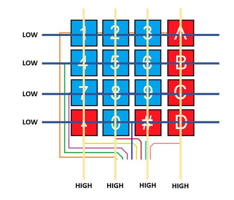
Step 2 – When a button is pressed, the entire button’s row is pulled low, as electric contact is now being made.
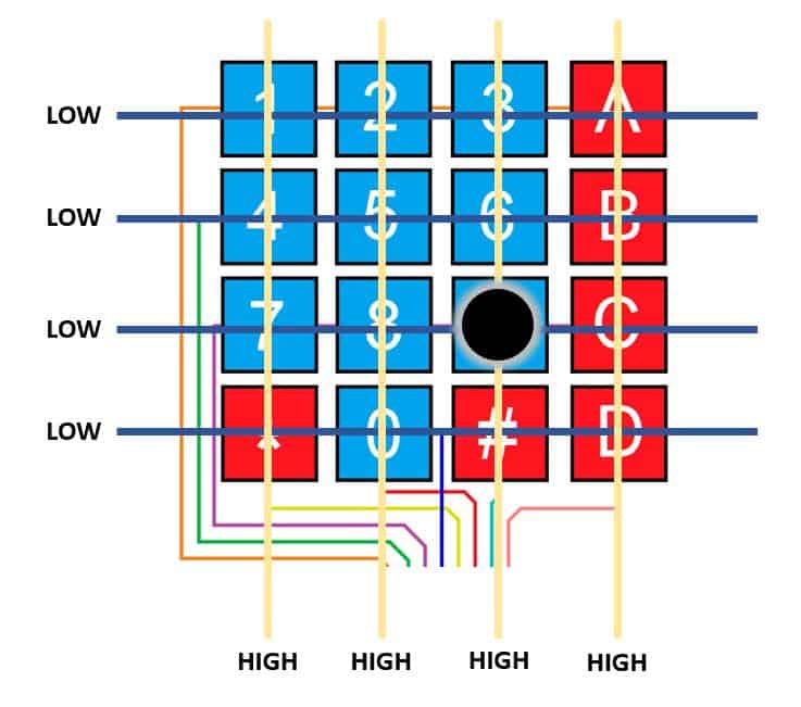
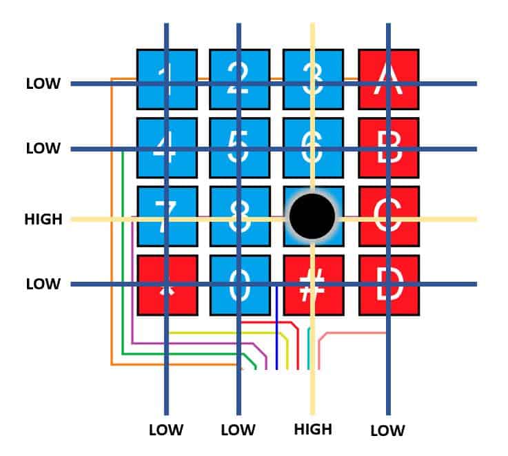
Step 3 – Since the Arduino now knows which column the button is in, it needs to figure out which row the button is in. This process simply requires the Arduino to switch all of the rows from high to low and then read each columns. Which one returns high identifies which button was pressed.
Step 4 – Finally, the Arduino has its answer as both the row and column of the pressed button will be high.
Connecting a Keypad to the Arduino
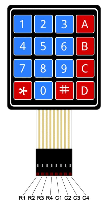
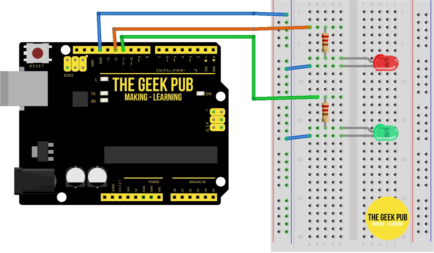
Most membrane keypads will use the same pinout. The pinout will be R1, R2, R3, R4, C1, C2, C3, C4 where R is for row and C is for column. Refer to the image below. If your keypad does not have this pinout you can use a multi-meter in continuity mode to test each pin while pressing each button.
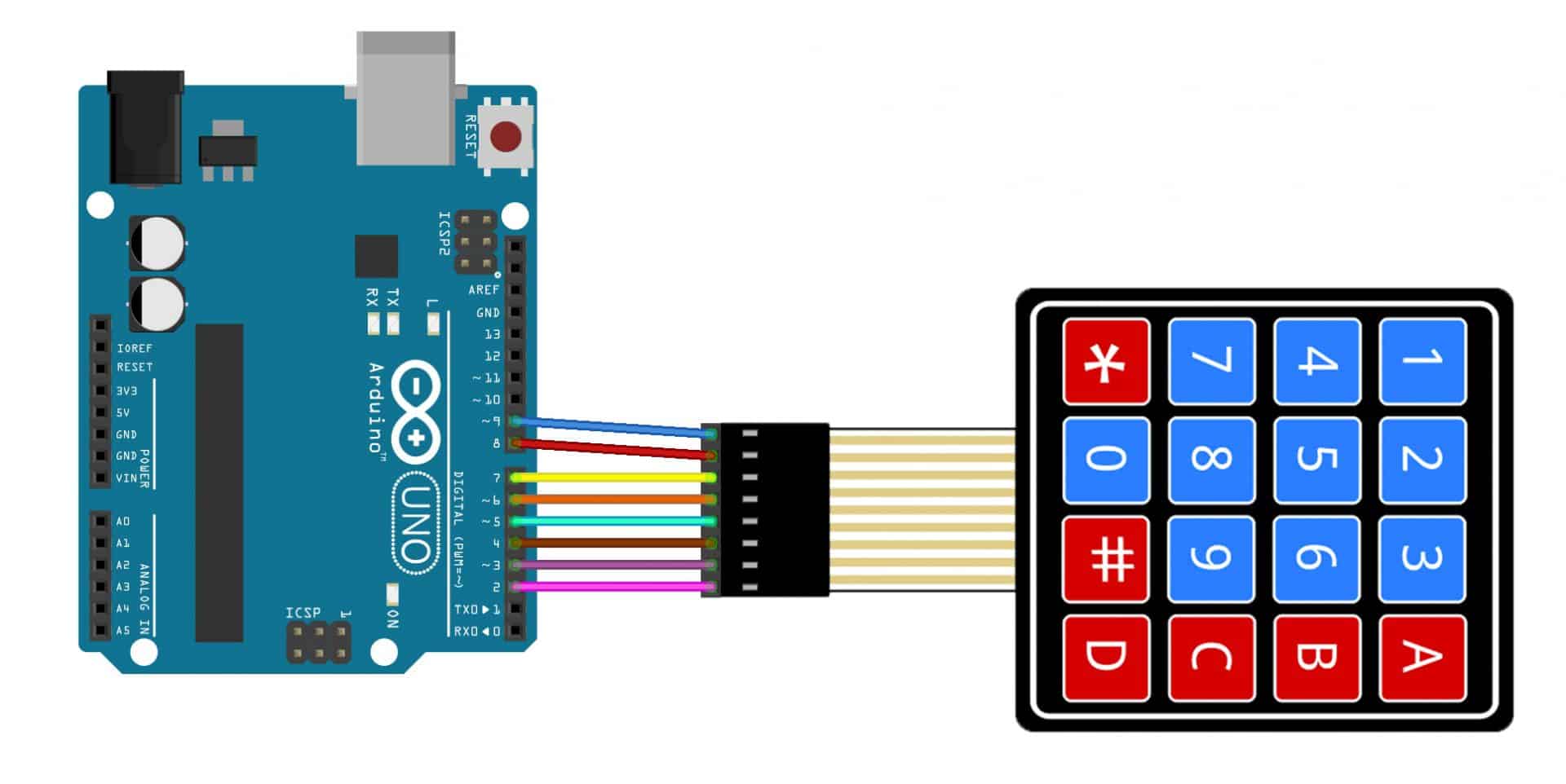
As we move forward in our How to Setup a Keypad on an Arduino tutorial, use the following diagram and chart to connect the keypad to your Arduino:
Keypad R1 –> Arduino PIN 9
Keypad R2 –> Arduino PIN 8
Keypad R3 –> Arduino PIN 7
Keypad R4 –> Arduino PIN 6
Keypad C1 –> Arduino PIN 5
Keypad C2 –> Arduino PIN 4
Keypad C3 –> Arduino PIN 3
Keypad C4 –> Arduino PIN 2
Coding for an Arduino Keypad
Now that we have the hardware ready to go, it is time to move on to the software side of things. Let’s put together the basic code for the keypad.
Use the following code snippet to get the Keypad working. Upload it to the Arduino Uno and then open the serial monitor.
[code language = "cpp"]
// The Geek Pub Keypad to Serial Console
// Freely distributable with attribution

#include <Keypad.h>

const byte KEYPAD_ROWS = 4;
const byte KEYPAD_COLS = 4;

char hexaKeys[KEYPAD_ROWS][KEYPAD_COLS] = {
  {'1', '2', '3', 'A'},
  {'4', '5', '6', 'B'},
  {'7', '8', '9', 'C'},
  {'*', '0', '#', 'D'}
};

byte rowPins[KEYPAD_ROWS] = {9, 8, 7, 6};
byte colPins[KEYPAD_COLS] = {5, 4, 3, 2};

Keypad GPKeypad = Keypad(makeKeymap(hexaKeys), rowPins, colPins, KEYPAD_ROWS, KEYPAD_COLS);

void setup() {
  Serial.begin(9600);
}

void loop() {
  char GPKey = GPKeypad.getKey();

  if (GPKey) {
    Serial.println(GPKey);
  }
}
[ / code]
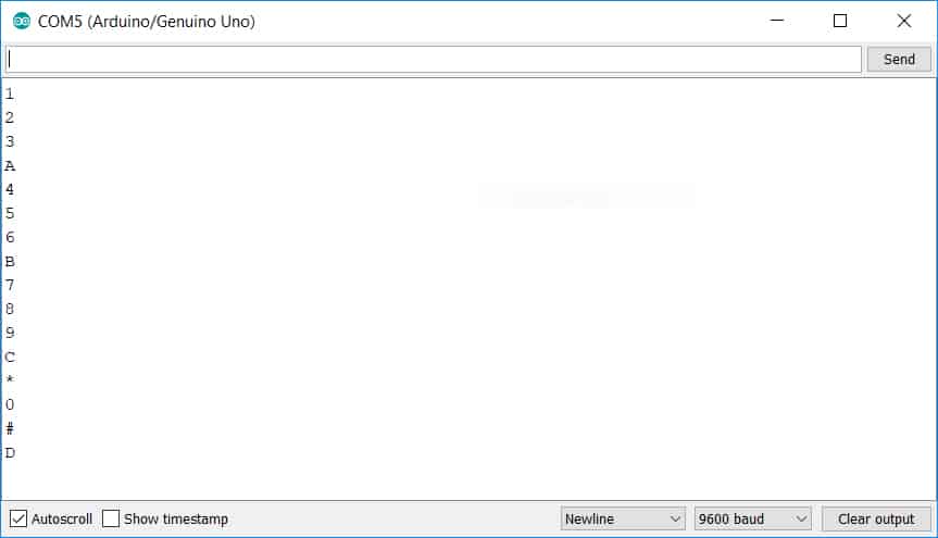
If you did everything correctly, as you press keys the serial monitor should show the output.
Controlling an LED with a Password
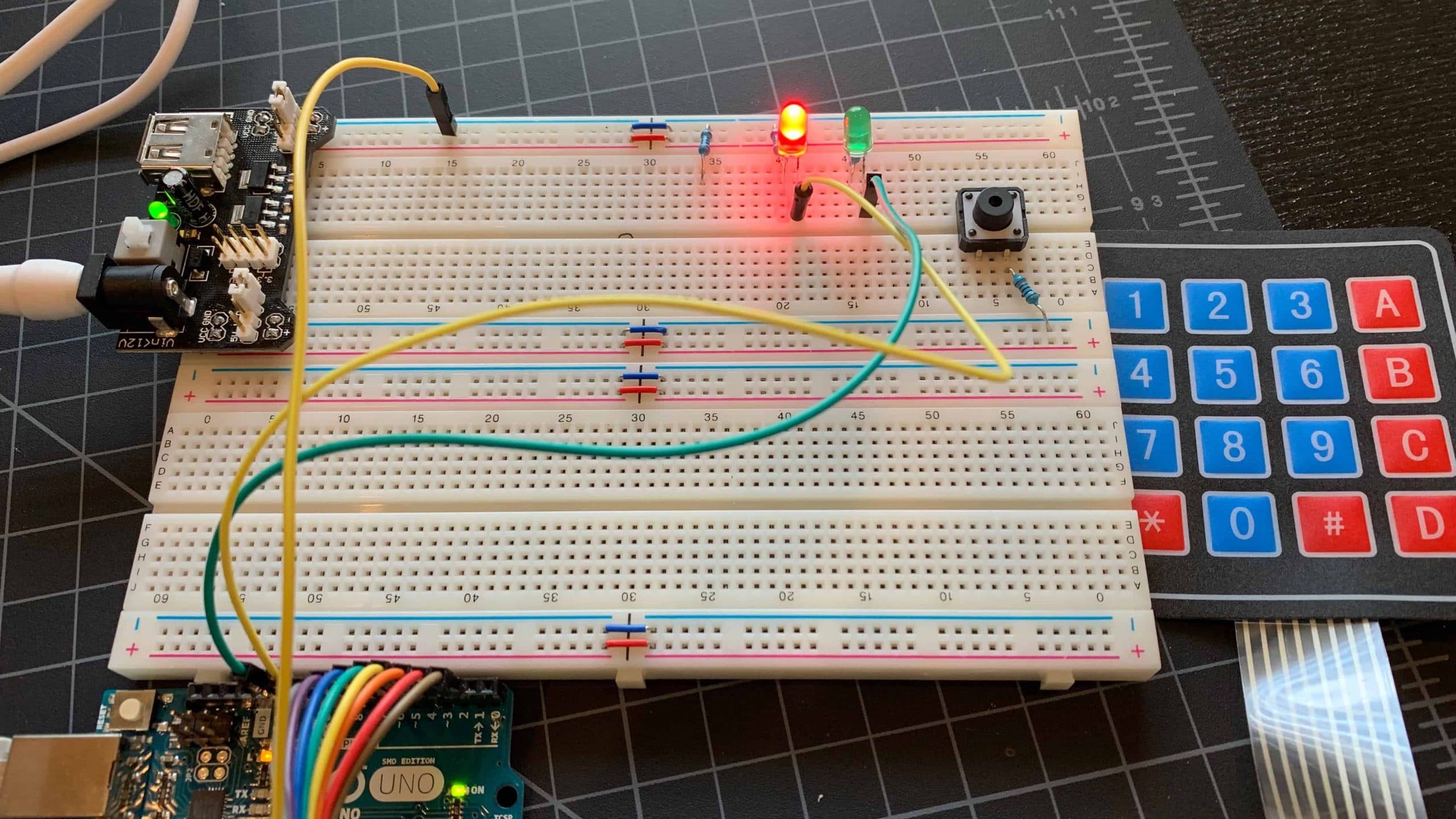
Next, let’s add some functionality. Add the following wires, LEDs, and resistors to your project while leaving the existing keypad wires intact.
Now let’s add a little more code. This code will look for our password and if we get it correct, it will turn on a green LED for 5 seconds. Otherwise, a red LED will stay lit indicating our keypad is locked.
GPKey = GPKeypad.getKey();

if (GPKey) {
  PW[myCounter] = GPKey;
  Serial.print(PW[myCounter]);
  myCounter++;
}

if (myCounter == Password_Length - 1) {

  if (!strcmp(PW, MasterPW)) {
    Serial.println("\nCorrect");
    digitalWrite(GreenLEDPin, HIGH);
    digitalWrite(RedLEDPin, LOW);
    delay(5000);
    digitalWrite(GreenLEDPin, LOW);
    digitalWrite(RedLEDPin, HIGH);
  }
  else {
    Serial.println("\nIncorrect");
    delay(1000);
  }
  Serial.print("\nEnter Password:");
  clearPW();
}
}
void clearPW() {
  while (myCounter != 0) {
    PW[myCounter--] = 0;
  }
  return;
}
[ / code]
Open the serial console and type your password of “1234”. Your screen should look this this:
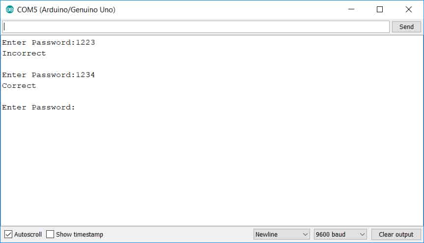
If you type the password wrong, the red LED will stay lit and the serial console will let you know your password was incorrect. If you type the password right the green LED will light for 5 seconds and the serial console will let you know the password was correct.
Expanding on the Keypad Code
Now that you’ve learned how to setup a keypad on an Arduino, you should take this project to the next level. You could add relays to control an automated door lock or turn a device on/off. You could even add a character LCD display instead of using the serial console!
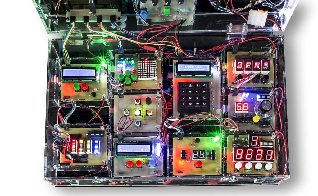
The local escape room near me has an Arduino “bomb diffusal” prop in one of their rooms and its a total blast. The fun you can have with an Arduino keypad project is almost endless!
Next Steps
Now you can move on to the next tutorial or go back to the list of Arduino Tutorials!