Blog
Raspberry Pi to Arduino I2C Communication
If you’ve been doing
Connecting a Raspberry Pi to an Arduino over I2C is Really Cool
There are many reasons to setup
It also allows me to write autonomous code on the Arduino that the
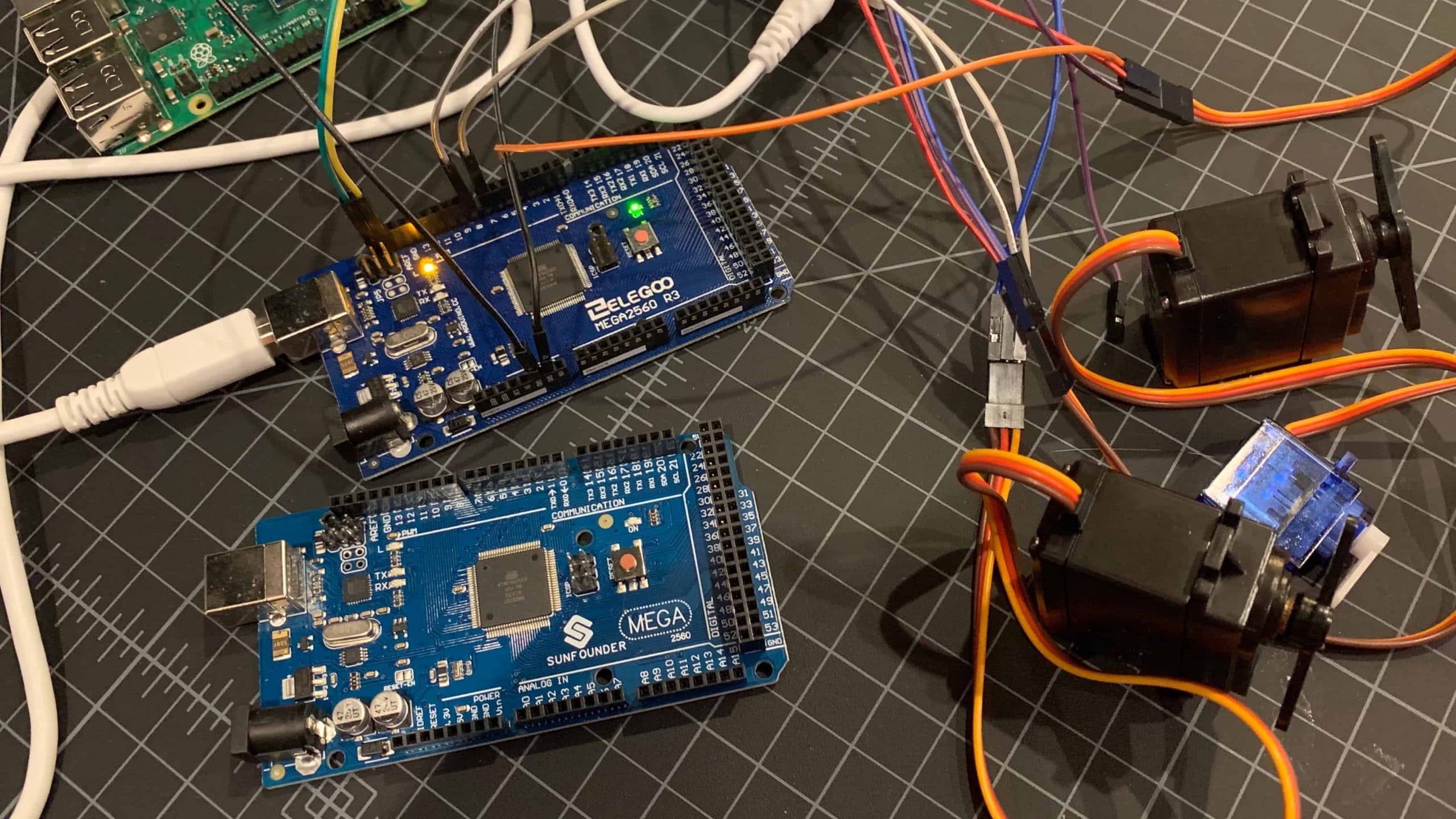
Wiring a Raspberry Pi to an Arduino for I2C Communication
Let’s start with the process of wiring the
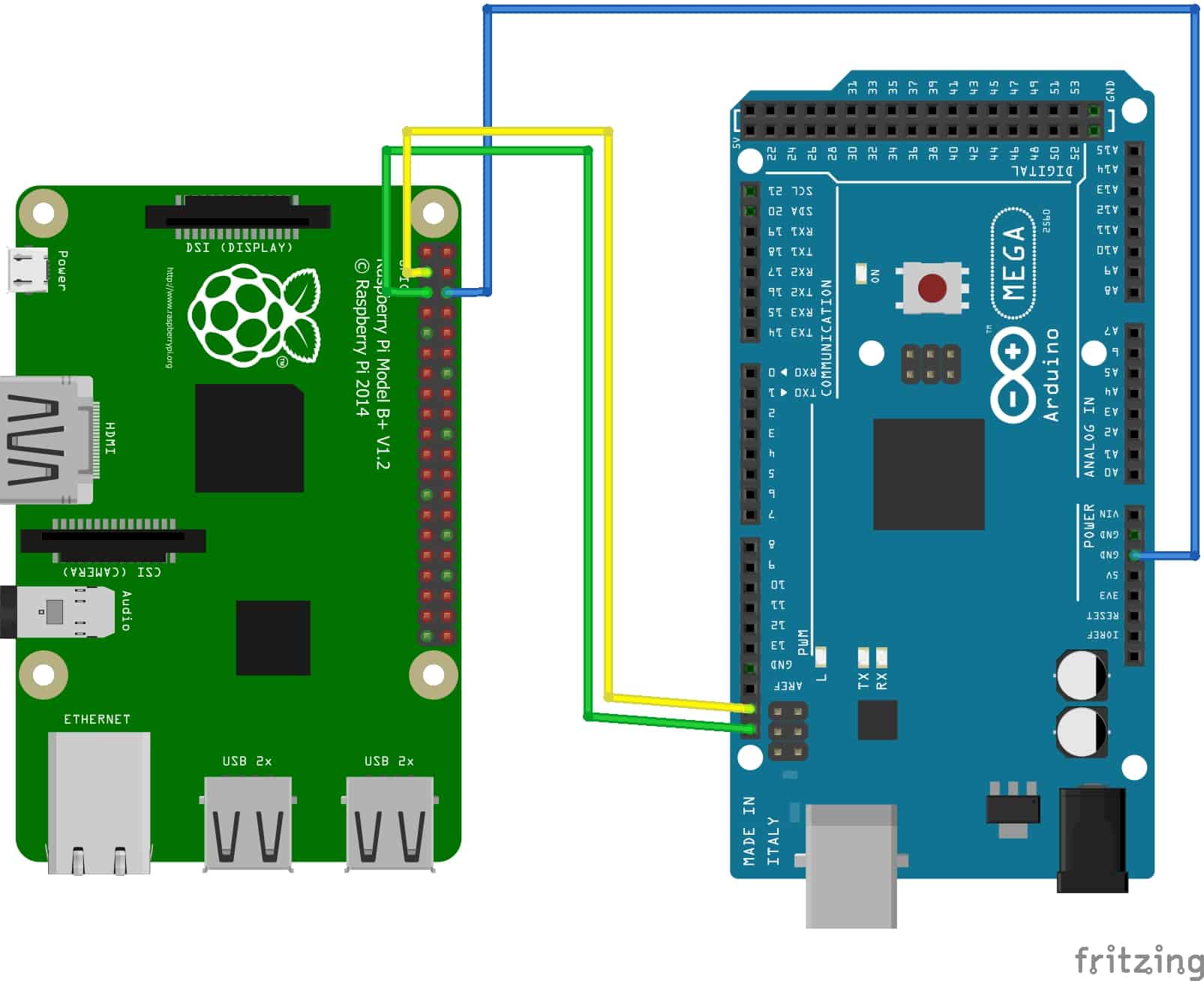
Raspberry Pi to Arduino I2C Communication: Single Arduino
Raspberry Pi SDA –> Arduino SDARaspberry Pi SCL –> Arduino SCLRaspberry Pi GND –> Arduino GND
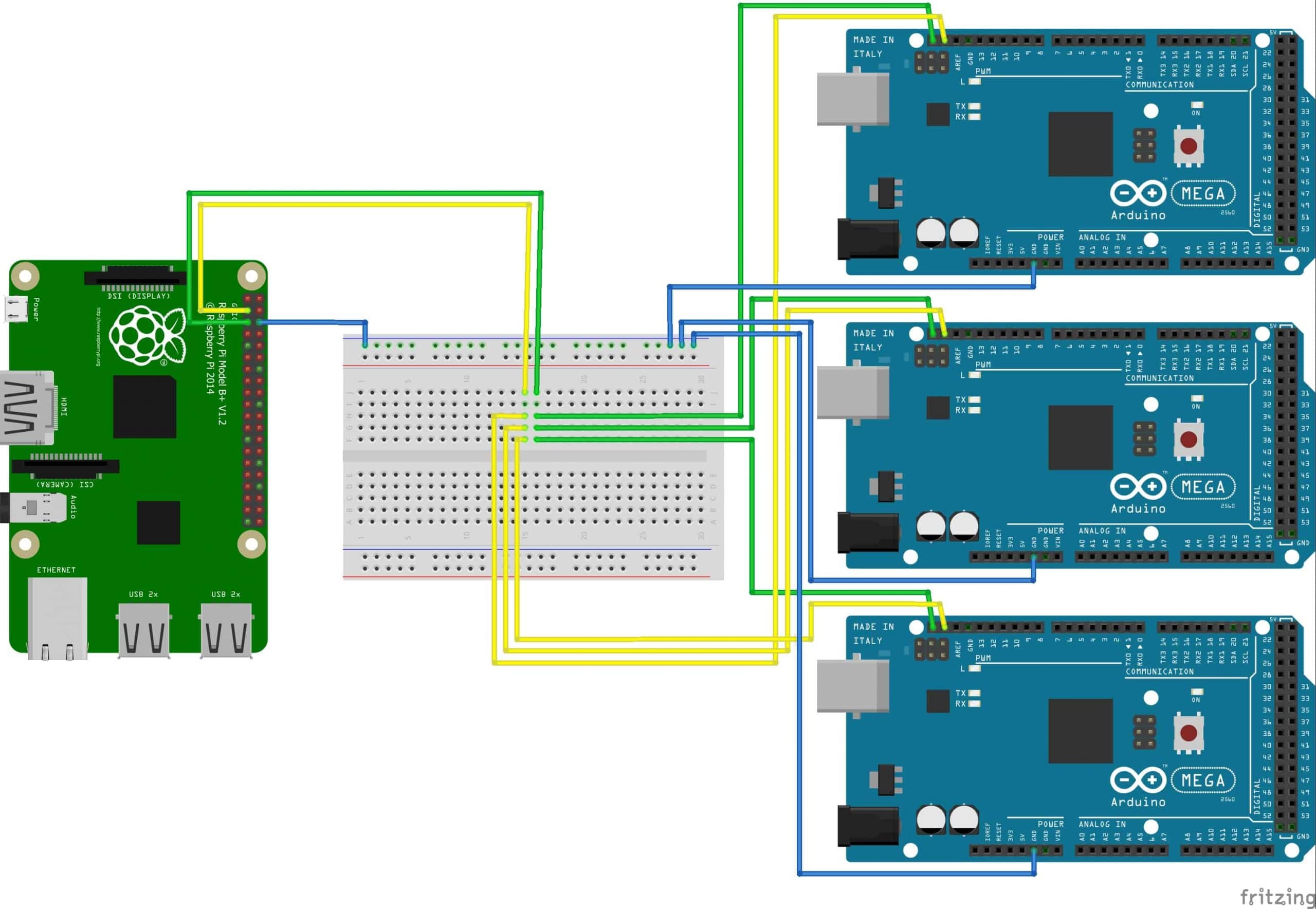
Raspberry Pi to Arduino I2C Communication: Multiple Arduinos
To connect multiple Arduinos to a
Raspberry Pi SDA –> Shared SDA on breadboardRaspberry Pi SCL –> Shared SCL on breadboardRaspberry Pi GND –> Shared GND on breadboard- All Arduino SDA –> Shared SDA on breadboard
- All Arduino SCL –> Shared SCL on breadboard
- All Arduino GND –> Shared GND on breadboard
 I am not going to go into how I2C works electrically in this how-to. There are plenty of resources on the web that already cover that topic. However, I do want to define some terms for you to help you better understand what these pins are doing and why they are wired the way they are.
- GND are the ground pins. It is important that all devices share a common ground for I2C to work properly.
- SCL is the Serial Clock pin. The master creates a timing pulse on this line that keeps all devices in sync.
- SDA is the Serial Data pin. This is the pin that reads and writes data on the bus.
- I2C Master is the device that owns the SCL line, starts, and stops all communication on the bus.
- I2C Slave is a device on the bus that listens and responds to communications from the master. These devices have individual addresses that are statically assigned via hardware or software.
Raspberry Pi to Arduino I2C Communication: Connecting Devices
From here you can connect devices to the Arduinos. This could be relays, servos, LEDs, motion sensors, or just about any other device you can think of. On the Arduino side they are controlled exactly the same as they would be without I2C being involved. For our little demo we will just control the internal on-board LED on pin 13. But feel free to change the pin number and connect your own LED or other device as you follow along. (If you’re new to Arduinos there is a surface mount LED connected to pin 13 on the board.)
The Raspberry Pi Python Code for I2C
On your
[code language=”python”]
# <keyword data-keyword-id="246">Raspberry Pi</keyword> to Arduino I2C Communication
# Python Code
import smbus
# Slave Addresses for Arduinos
ARDUINO_1_ADDRESS = 0x04 # I2C Address of Arduino 1
ARDUINO_2_ADDRESS = 0x05 # I2C Address of Arduino 2
ARDUINO_3_ADDRESS = 0x06 # I2C Address of Arduino 3
# Create the I2C bus
I2Cbus = smbus.SMBus(1)
aSelect = input("Which Arduino (1-3): ")
bSelect = input("On or Off (on/off): ")
if aSelect == 1:
SlaveAddress = ARDUINO_1_ADDRESS
elif aSelect == 2:
SlaveAddress = ARDUINO_2_ADDRESS
elif aSelect == 3:
SlaveAddress = ARDUINO_3_ADDRESS
else:
# quit if you messed up
quit()
# also quit if you messed up
if bSelect != "on" or bSelect != "off": quit()
BytesToSend = ConvertStringsToBytes(bSelect)
I2Cbus.write_i2c_block_data(SlaveAddress, 0x00, BytesToSend)
print("Sent " + SlaveAddress + " the " + bSelect + " command.")
# This function converts a string to an array of bytes.
def ConvertStringToBytes(src):
converted = []
for b in src:
converted.append(ord(b))
return converted</pre>
[/code]
The Arduino Code for I2C
Use the following code on each Arduino. Be sure to change the slave address for each device so they are unique. If two devices share the same address things will not work.
[code language=”cpp”]
//Arduino code to receive I2C communication from <keyword data-keyword-id="247">Raspberry Pi</keyword>
#include &amp;lt;Wire.h&amp;gt;
// Define the slave address of this device.
#define SLAVE_ADDRESS 0x04
// #define SLAVE_ADDRESS 0x05
// #define SLAVE_ADDRESS 0x06
// string to store what the RPi sends
String str_recieved_from_RPi = "";
void setup() {
// setup the LED
pinMode(LED_BUILTIN, OUTPUT);
// begin running as an I2C slave on the specified address
Wire.begin(SLAVE_ADDRESS);
// create event for receiving data
Wire.onReceive(receiveData);
}
void loop() {
// nothing needed here since we’re doing event based code
}
void receiveData(int byteCount) {
while ( Wire.available()) {
str_recieved_from_RPi += (char)Wire.read();
}
// turn on or off the LED
if (str_recieved_from_RPi == "on") {
digitalWrite(LED_BUILTIN, HIGH);
}
if (str_recieved_from_RPi == "off") {
digitalWrite(LED_BUILTIN, LOW);
}
str_recieved_from_RPi = "";
}
[/code]
[amazon_link asins=’B01H4ZLZLQ,B01LPLPBS8,B01EV6LJ7G,B01EV70C78′ template=’ProductGrid’ store=’murraynet-20′ marketplace=’US’ link_id=’c98daf12-a9c4-49c2-8a92-850bbd2bb86f’]


5
I see a lot of comments on as m different forums about logic level shifting between RPI and Arduino because their VCC is different. You don’t appear to worry about that. Is there a reason?
It depends on what you are doing. Sometimes its needed, sometimes its not.
Hi Mike,
many thanks for this interesting post.
I think there is a little problem with the html-code though. I think the line
#include “some html code”
should actually say:
#include
Best regards,
Andreas
4.5
5