Blog
Easy Arduino Dice Circuit
In this project tutorial we’re going to build a super easy Arduino dice circuit. It’s a great learning project and one of the first project a lot of people new to the Arduinos or micro-controllers in general like to do because it is simple to understand. We’ve added a neat twist to our dice circuit to make it a little more exciting.
The Arduino Dice Circuit
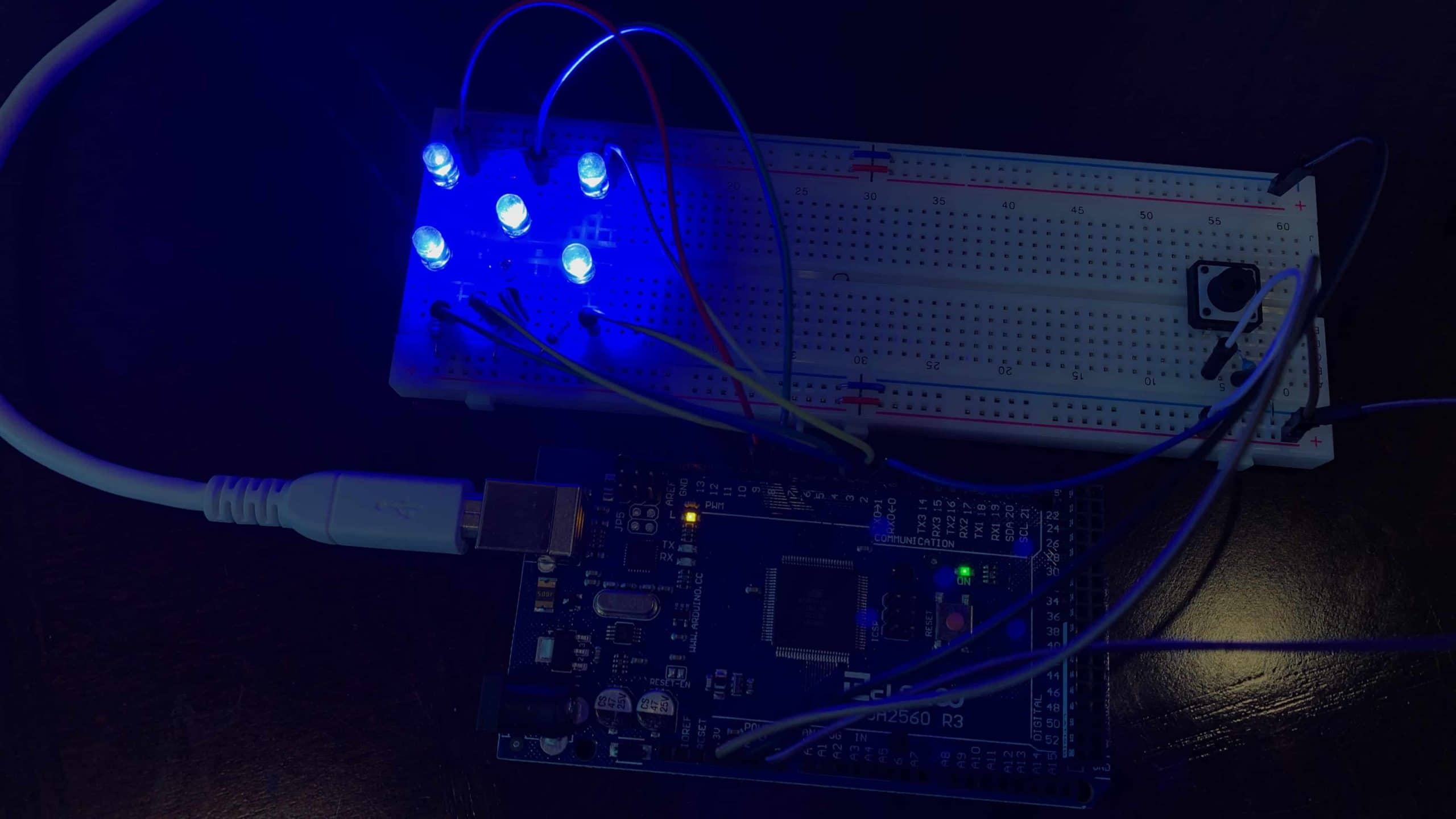
In this project we’ll use 7 LEDs to make up our dice face, along with a simple button to activate the random selection and displace of our number. I’m going to use some really cool clear blue LEDs. Of course, we’ll need some resistors, a breadboard and some wires as well.
You could easily take this project to the next level (and we may do so in a future project) by making multiple dice and putting it into a 3D printed case!
Parts List for this Project
As always, here’s a quick parts list for this project:
| QTY | PART/LINK | ||
|---|---|---|---|
| 1X | [icon name=”microchip” prefix=”fas”] | Arduino Uno | [icon name=”cart-plus” prefix=”fas”] |
| 1X | [icon name=”usb” prefix=”fab”] | USB Type B Cable | [icon name=”cart-plus” prefix=”fas”] |
| 1X | [icon name=”th” prefix=”fas”] | Solderless Breadboard | [icon name=”cart-plus” prefix=”fas”] |
| 1X | [icon name=”grip-lines” prefix=”fas”] | Jumper Wire Kit | [icon name=”cart-plus” prefix=”fas”] |
| 1X | [icon name=”lightbulb” prefix=”fas”] | LED Kit | [icon name=”cart-plus” prefix=”fas”] |
| 1X | [icon name=”ellipsis-h” prefix=”fas”] | Resistor Kit (220 Ohm) | [icon name=”cart-plus” prefix=”fas”] |
Some of these links are affiliates. If you use them it costs you nothing, but we get a small commissions and that helps us keep making content for you!
Wiring up the Arduino Dice Circuit
Wiring up the Arduino dice circuit isn’t much more complicated than our traffic light project. We’re just going from 3 LEDs to 7 and adding a simple button to start the process.
We’ve put together a super simple wiring diagram for this project to make it as simple as possible to understand. Here’s what you need to do:
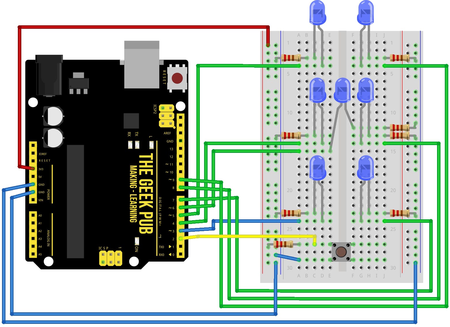
Some of the more advanced Arduino hobbyist will immediately recognize that there are simpler ways of wiring this board to reduce wires and clutter. You’ll likely notice similar issues in the code we’ve posted for this project. This is because we want the concepts to be as easy as possible to understand. But feel free to leave a comment below and tell us what you’d change to make this better!
The main thing to understand is that each LED needs a 100 Ohm current limiting resistor to keep the LED from popping. Additionally, the button (or momentary switch) also needs a 10K Ohm resistor in order to pull up the circuit so that it’s not “floating”. The Arduino needs the circuit to be either HIGH or LOW at all times.
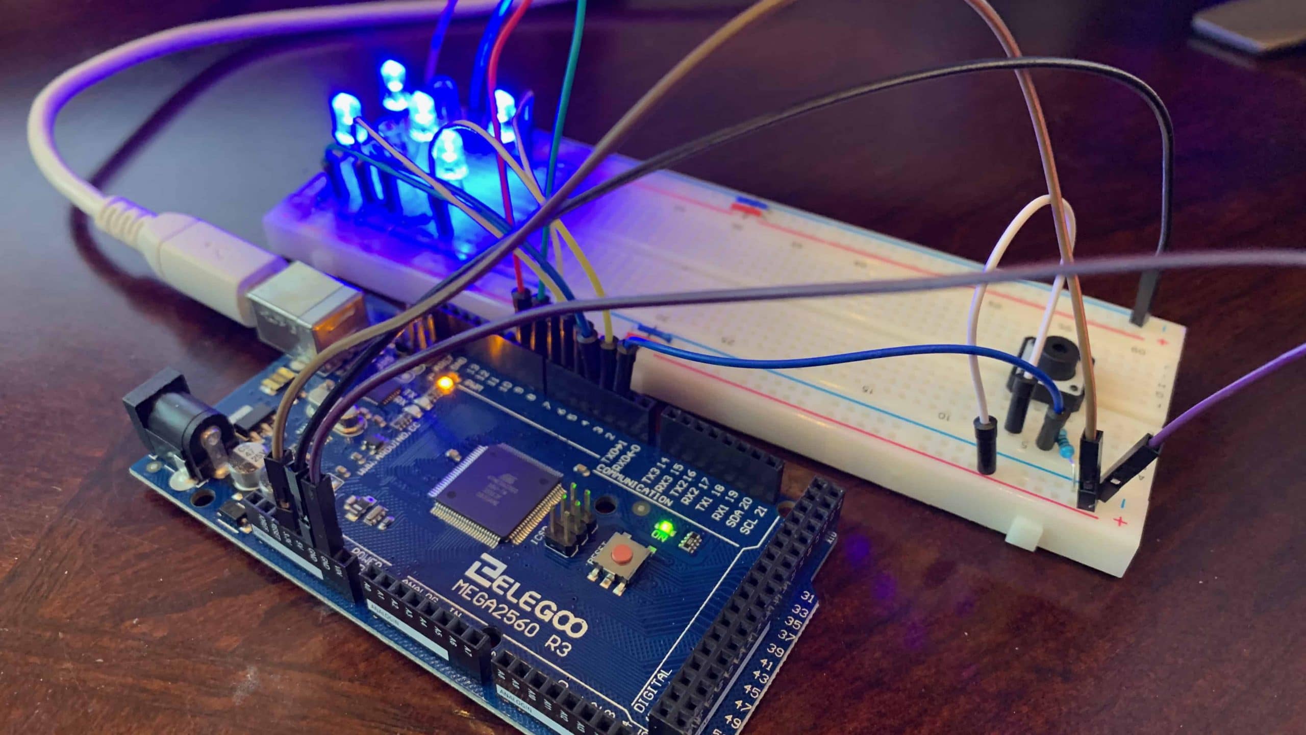
In the wiring diagram above we’ve arrange the LEDs int eh shape of a die face. However, we’ve moved the quite a bit apart from each other to make the diagram easier to comprehend. In our actual build (as you can see in the pictures) we compressed them to make them closer resemble a die!
Arduino Dice Circuit Code
Now it’s time to program the Arduino and make our dice circuit actually do something! The program needs to do two very basic things. The first is to randomly select a number between 1 and 6. The second is to display that number on the LEDs as if they were a die.
About Generating Random Numbers
To generate random numbers on the Arduino we’ll need to use a random number generator. It’s important to understand that random numbers in the computer world are never truly random (some even believe there is no such thing as random numbers in the real world!). Because each time the Arduino sketch executes it will create a long number and that number is always the same.
To get around this problem, we will use the randomSeed() function. This functions reads the value of an analog pin that’s not being used. It will be “floating” and its value will be based on a lot of unknown things such as humidity, temperature, etc. in the environment. Then later we will use the random() function to generate a number using that seed. Without randomSeed(), our use of random() wouldn’t be very random each time we restarted the sketch.
So let’s get started coding our Arduino Dice Circuit!
First things first, let’s define all of our components using variables. This isn’t necessary per say, but it sure makes the code easier to understand.
int triggerButton = 2;
int bottomLeftLED = 3;
int middleLeftLED = 4;
int upperLeftLED = 5;
int middleLED = 6;
int bottomRightLED = 7;
int middleRightLED = 8;
int upperRight = 9;
Next, we’ll create a variable that will contain the value of our random number and ultimately the value of our die.
long randomDiceNumber;
In the setup() function, we’re going to define all of the pins so the Arduino knows our LEDs are OUTPUT pins and the button is an INPUT pin. Additionally, this is where we populate our randomSeed(). We’ll use analog pin 0 for this.
void setup(){
// set all of the LED pins to OUTPUT
pinMode(bottomLeftLED, OUTPUT);
pinMode(middleLeftLED, OUTPUT);
pinMode(upperLeftLED, OUTPUT);
pinMode(middleLED, OUTPUT);
pinMode(bottomRightLED, OUTPUT);
pinMode(middleRightLED, OUTPUT);
pinMode(upperRight, OUTPUT);

// set the button to INPUT
pinMode(triggerButton, INPUT);

// create a seed for our random numbers
randomSeed(analogRead(0));
}
Adding a little flair to this project to make it a little more fun and exciting when showing it to others, we’ve put a little flashing sequence in there. This is another one of those sections that the code could be much more compact. Leave a comment below if you know how (it could be only two lines). But we wanted the beginner to be able to understand it! Basically it cycles quickly through every number (5 times) and then waits 300ms before selecting and showing the actual number. This gives the impression that the Arduino dice circuit is “thinking”. This portion of the code us purely optional!
This is followed by in if statement to check the state of the button and an if statement to present the number.
for (int i=0; i <= 5; i++){
  MakeOne();
  delay(60);
  clearDice();
  MakeTwo();
  delay(60);
  clearDice();
  MakeThree();
  delay(60);
  clearDice();
  MakeFour();
  delay(60);
  clearDice();
  MakeFive();
  delay(60);
  clearDice();
  MakeSix();
  delay(60);
  clearDice();
  delay(60);
  }
delay(300);
Finally, you’ll see a a function for showing each die number, along with a function to clear the number.
void MakeFour()
  {
  digitalWrite(upperLeftLED, HIGH);
  digitalWrite(bottomLeftLED, HIGH);
  digitalWrite(upperRight, HIGH);
  digitalWrite(bottomRightLED, HIGH);
  }

void clearDice()
  {
  digitalWrite(bottomLeftLED, LOW);
  digitalWrite(middleLeftLED, LOW);
  digitalWrite(upperLeftLED, LOW);
  digitalWrite(middleLED,LOW);
  digitalWrite(bottomRightLED, LOW);
  digitalWrite(middleRightLED, LOW);
  digitalWrite(upperRight, LOW);
  }
The Complete Arduino Dice Code
Here’s the listing of the completed code that you can cut and paste into the Arduino IDE as a sketch for your project!
// Easy Arduino Dice Circuit ©The Geek Pub, LLC - Mike Murray 2019
// Freely distributable with attribution and link to TheGeekPub.com

// We need to define a trigger Button for our dice
int triggerButton = 2;

// Dice LEDs
int bottomLeftLED = 3;
int middleLeftLED = 4;
int upperLeftLED = 5;
int middleLED = 6;
int bottomRightLED = 7;
int middleRightLED = 8;
int upperRight = 9;

long randomDiceNumber;

void setup(){
// set all of the LED pins to OUTPUT
	pinMode(bottomLeftLED, OUTPUT);
	pinMode(middleLeftLED, OUTPUT);
	pinMode(upperLeftLED, OUTPUT);
	pinMode(middleLED, OUTPUT);
	pinMode(bottomRightLED, OUTPUT);
	pinMode(middleRightLED, OUTPUT);
	pinMode(upperRight, OUTPUT);

// set the button to INPUT
	pinMode(triggerButton, INPUT);

// enable the serial console for troubleshooting (optional)
	Serial.begin(9600);

// create a seed for our random numbers
	randomSeed(analogRead(0));
}

void loop(){
//Read our triggerButton if high then run dice
	if (digitalRead(triggerButton) == HIGH){

// give the impression the dice is "thinking" by cycling numbers 5 times quickly
// (yes, this routing could be written in two lines, but I left it this way to make it simple to undestand)
		for (int i=0; i <= 5; i++){
			MakeOne();
			delay(60);
			clearDice();
			MakeTwo();
			delay(60);
			clearDice();
			MakeThree();
			delay(60);
			clearDice();
			MakeFour();
			delay(60);
			clearDice();
			MakeFive();
			delay(60);
			clearDice();
			MakeSix();
			delay(60);
			clearDice();
			delay(60);
		}
// pause 300ms blank before selecting and showing the number
		delay(300);

		randomDiceNumber = random(1, 7);
		delay(100);
		Serial.println(randomDiceNumber);

		if (randomDiceNumber == 6){
			MakeSix();
		}
		if (randomDiceNumber == 5){
			MakeFive();
		}
		if (randomDiceNumber == 4){
			MakeFour();
		}
		if (randomDiceNumber == 3){
			MakeThree();
		}
		if (randomDiceNumber == 2){
			MakeTwo();
		}
		if (randomDiceNumber == 1){
			MakeOne();
		}
		delay(5000);
		clearDice();
	}
}

// Thes functions create our dice

// make a six
void MakeSix()
{
	digitalWrite(bottomLeftLED, HIGH);
	digitalWrite(middleLeftLED, HIGH);
	digitalWrite(upperLeftLED, HIGH);
	digitalWrite(bottomRightLED, HIGH);
	digitalWrite(middleRightLED, HIGH);
	digitalWrite(upperRight, HIGH);
}

// make a five
void MakeFive()
{
	digitalWrite(upperLeftLED, HIGH);
	digitalWrite(bottomLeftLED, HIGH);
	digitalWrite(middleLED, HIGH);
	digitalWrite(upperRight, HIGH);
	digitalWrite(bottomRightLED, HIGH);
}

// make a four
void MakeFour()
{
	digitalWrite(upperLeftLED, HIGH);
	digitalWrite(bottomLeftLED, HIGH);
	digitalWrite(upperRight, HIGH);
	digitalWrite(bottomRightLED, HIGH);
}

//make a three
void MakeThree()
{
	digitalWrite(upperLeftLED, HIGH);
	digitalWrite(middleLED, HIGH);
	digitalWrite(bottomRightLED, HIGH);
}

// make a two
void MakeTwo()
{
	digitalWrite(bottomRightLED, HIGH);
	digitalWrite(upperLeftLED, HIGH);
}

// make a one
void MakeOne(){
	digitalWrite(middleLED, HIGH);
}

// This routine clears the dice back to zero
void clearDice(){
	digitalWrite(bottomLeftLED, LOW);
	digitalWrite(middleLeftLED, LOW);
	digitalWrite(upperLeftLED, LOW);
	digitalWrite(middleLED,LOW);
	digitalWrite(bottomRightLED, LOW);
	digitalWrite(middleRightLED, LOW);
	digitalWrite(upperRight, LOW);
}
We hope you enjoyed this project! It’s a great learning project for first time Arduino developers. Leave a comment below to let us know how this went for you and any changes you’d make!
Next Steps
Now that you’ve finished this tutorial you can go on the the next tutorial or back to the index.


Gday Mike
Thanks for posting this project. It will be an excellent unit for my Technology Mandatory Digital Media class.
It is terrific the way you made it as simple as possible with great instructions and explanations.
Throughout the task you mentioned how the wiring and coding could easily be simplified. Could you please find the time to send me these
adaptations as I would like to have the solutions available for my extension students (they will appreciate the challenge and I would like to look like I know the solution)
Thanks in advance for your time and effort
Regards
Paul
Paul,
let me have your contact details, I have an advanced yet simplified version.
Thanks Mike
Your post inspired me to make it and after a little development I came yo the following conclusions:
1. It could be wired with only 4 groups of LEDs.
2. The pin control could be with PORTB= where the control bytes can be stored in an array so being accessed via array indexing.
Thank you