Sensor Wiki: KY-010 Light Barrier Module
This wiki article covers the KY-010 light barrier module (sometimes called a photo interrupter module). Included are wiring diagrams, code examples, pinouts, and technical data. The signal pin will go high when an object blocks light from passing between its emitter and detector.
Content
- Sensor/Module Image Gallery
- Description and Technical Data
- Device Pinout
- Projects that use this Sensor/Module
- Code Examples
- Code example for Arduino
- Code example for Raspberry Pi

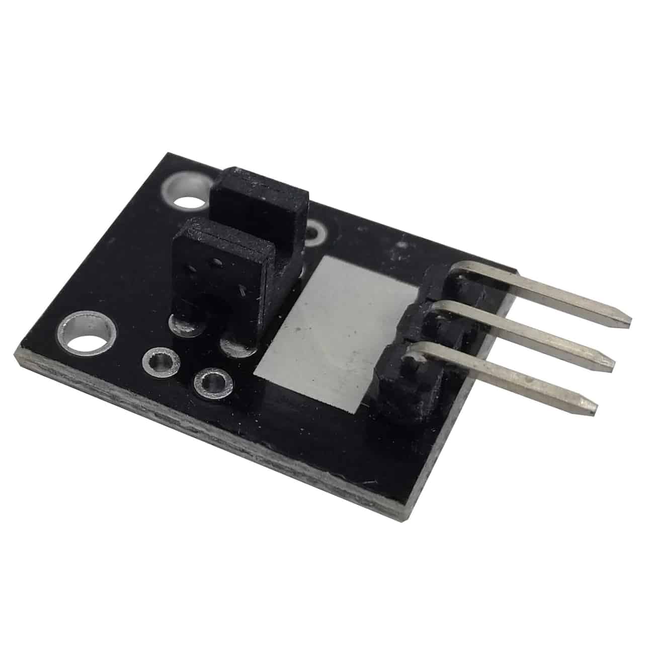
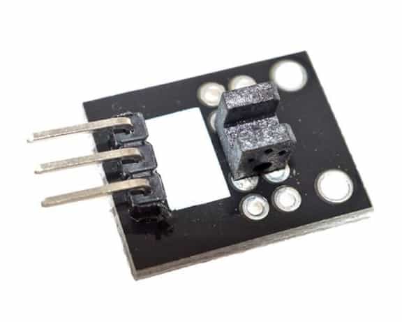
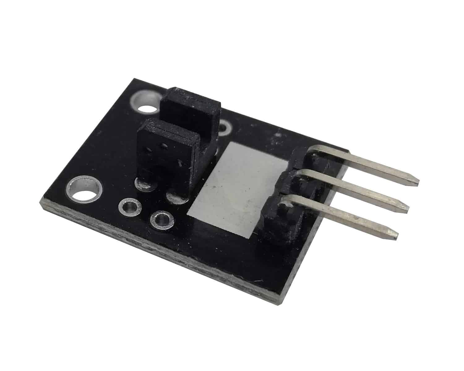
Sensor Module Image Gallery
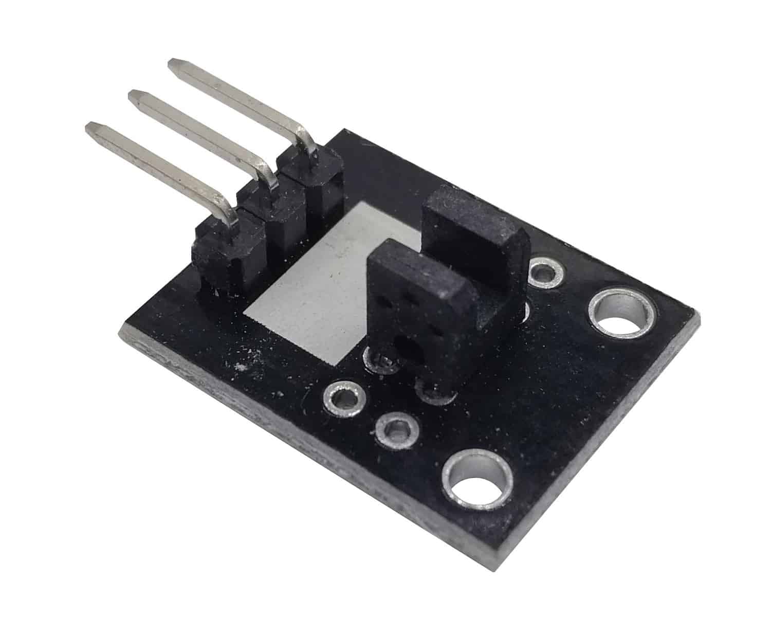
Description and Technical Data
The KY-010 light barrier module / photo interrupter module is a 3-pin module that brings its signal pin HIGH when an object blocks light from traveling between its emitter and sensor. This sensor is great for detecting the swipe of a card through a slot or other applications where detecting something opening or closing is necessary.
Tech Specs for the KY-010 module:
- Min/Max Operating Voltage 3.3V to 5V DC
- Dimensions: 0.728in x 0.591in( 18.5mm x 15mm)
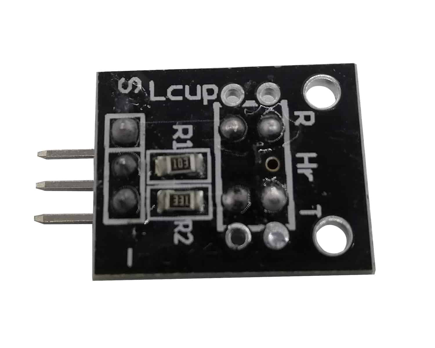
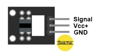
Device Pinout & Schematics
This module has three pins: GND, Vcc+, and Signal.
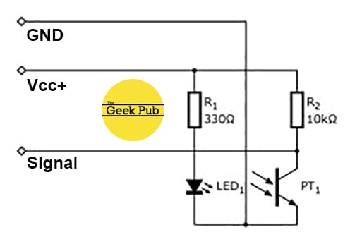
The schematic for the KY-010 photo interrupter module:
Our Projects that Use this Sensor
We do not currently have an projects that feature the KY-006, but check back soon!
Code Examples
You’ll find below code examples of using the KY-010 photo interrupter / light barrier module with both Arduino and Raspberry Pi (Python).
KY-010 Light Barrier / Photo Interrupter Code Example for Arduino
In this KY-010 Light Barrier module example code, we will write “Detected!” to the serial console when the sensor detects an object in its path.
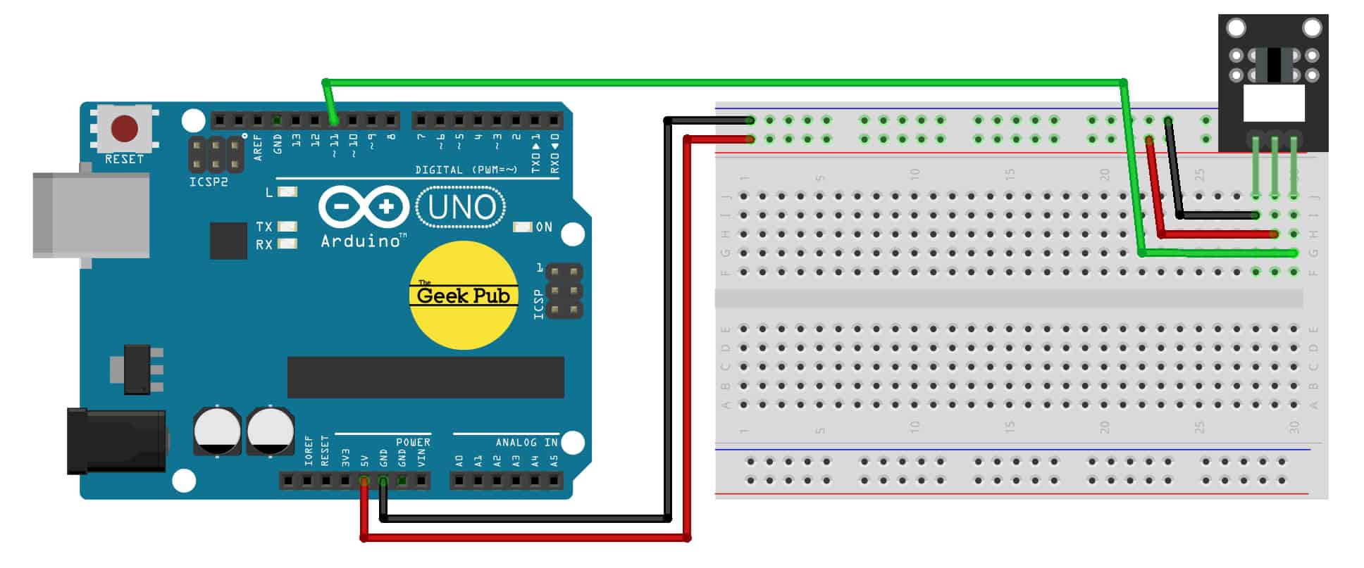
Arduino Wiring:
- KY-010 Module GND to Arduino GND
- KY-010 Module Signal to Arduino PIN 11
- KY-010 Module Vcc+ to Arduino 5V
int SensorPIN = 10; // define the sensor pin
int val;

void setup ()
{
pinMode (SensorPIN, INPUT) ; // define the sensor pin as an input
Serial.begin(9600);
}

void loop ()
{
val = digitalRead (SensorPIN) ; // read the sensor value.
if (val == HIGH) // if the value is high do this!
{
Serial.print("Detected!");
}

}
KY-010 LIGHT BARRIER MODULE CODE EXAMPLE FOR RASPBERRY PI
The following code example is for the Raspberry Pi using the Python programming language. This code will write “Detected!” to the terminal window when the light sensor detects an object.
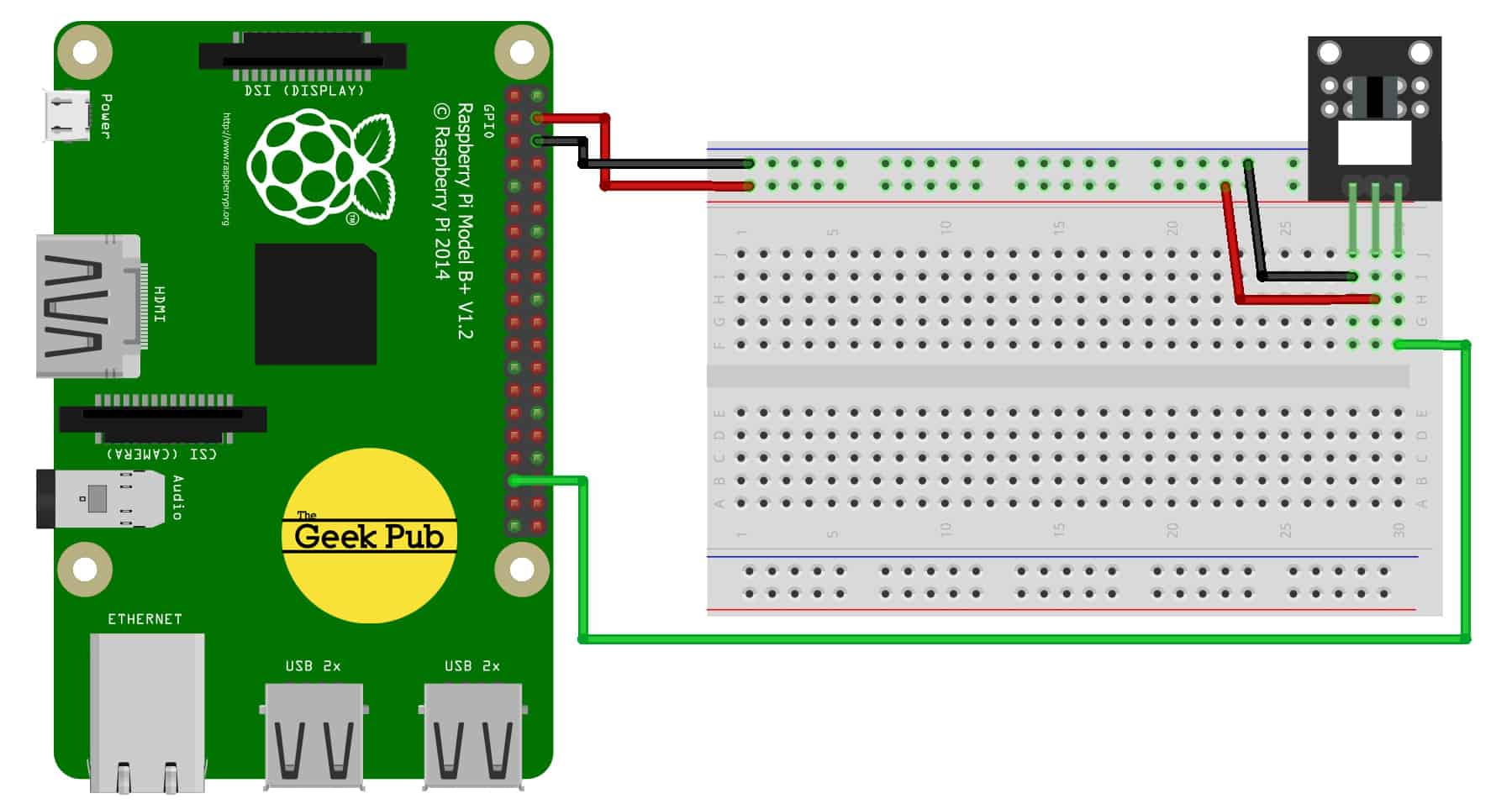
Raspberry Pi Wiring:
- KY-006 Module GND to Raspbery Pi GND
- KY-006 Module Signal to Raspberry Pi PIN 18 (GPIO 24)
- KY-006 Module Vcc+ to Raspberry Pi PIN 2
# import modules
import RPi.GPIO as GPIO
import time

GPIO.setmode(GPIO.BCM)

GPIO_PIN = 24
GPIO.setup(GPIO_PIN, GPIO.IN, pull_up_down = GPIO.PUD_DOWN)

def outputFunction(null):
print("Detected!")

GPIO.add_event_detect(GPIO_PIN, GPIO.RISING, callback=outputFunction, bouncetime=100)

while True:
time.sleep(1)
We hope this wiki article has been helpful to you. Please leave a comment below if you have any questions or comments, as we try to keep these articles constantly up to date.