Blog
JAMMA Pinout (PDF)
Whether you’ve just started learning about arcades or you’re a die hard arcade fan, you’ve no doubt heard JAMMA mentioned in conversations. JAMMA is an industry standard connector used on arcade boards. Standards make things easier to work on and understand! In this article, we’re going to cover the JAMMA wiring and connector and provide the JAMMA pinout (PDF included).
What is JAMMA?
JAMMA stands for “Japan Amusement Machine and Marketing Association”. This organization created the standard for the JAMMA connector back in 1986. By having a standard connector on arcade boards, this simplifies conversion of a cabinet from one game to another. Converting a cabinet became as simple as pulling and replacing the board and then changing the decals.
The majority of games do not use the entire JAMMA connector, rather opting for a smaller subset of the pins that satisfy that games controller needs. However, some games such as Mortal Kombat have extra buttons and therefore must have extra connectors for these additional controls!
The JAMMA connector is a .187 inch (3.96 mm) card-edge connector. Female pins will be found on the harness, and make pins on the board’s header.
JAMMA Wiring and JAMMA Pinout (PDF included)
As mentioned the JAMMA connector is female on the harness side and male on the board side. It’s a card-edge style consisting of 56 total pins. Although some JAMMA connectors are keyed, not all are making it is possible to plug the JAMMA connector in upside down. Doing so is likely to cause damage to the PCB components.
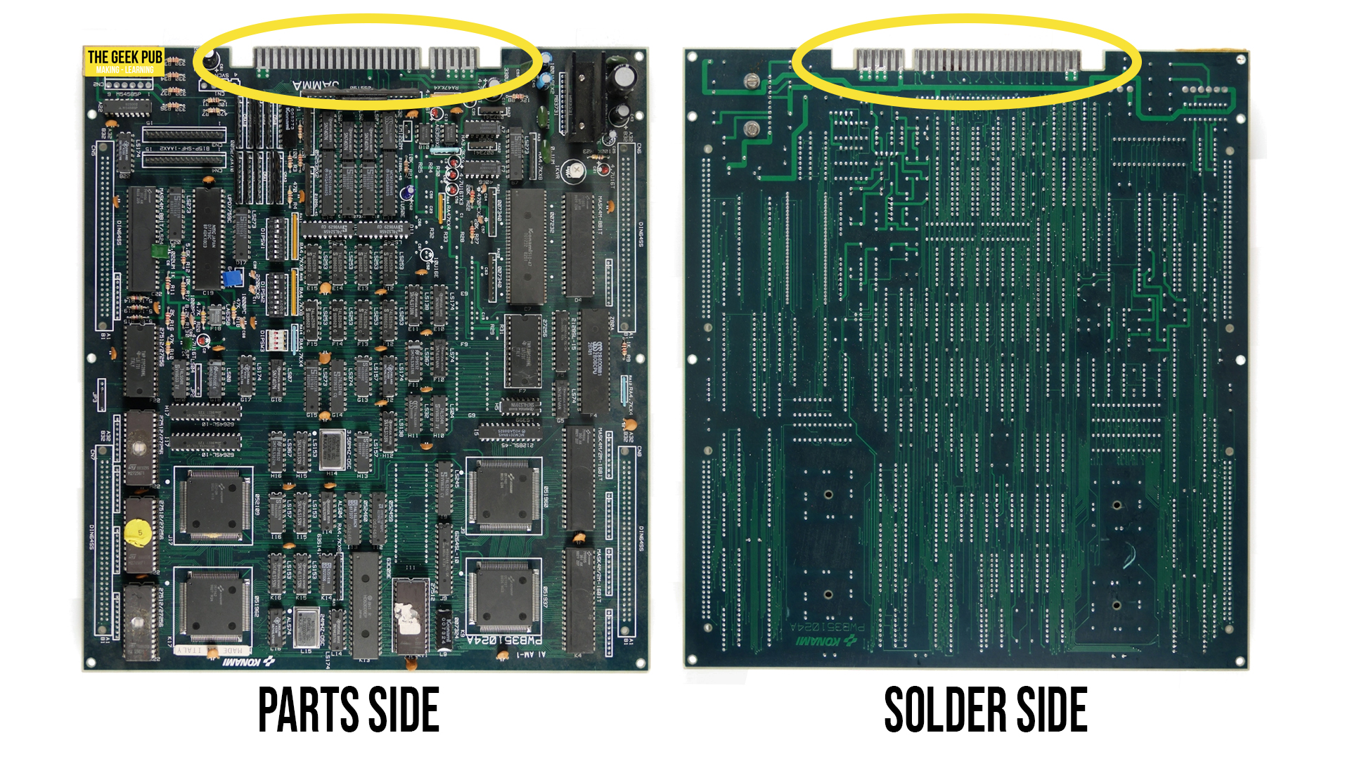
Often you’ll see JAMMA pinouts and wiring diagram refer to the connector by its sides: Solder Side and Parts Side. This means exactly what it sounds like. Circuit boards (generally) have parts on the top, and the solder pins on the bottom. When referencing these terms on a JAMMA connector, we mean the parts side goes up and the solder side goes down in orientation to the PCB.
You can see on the picture below of a Teenage Mutant Ninja Turtles board how this connector sits, illustrating both sides of the board.
JAMMA Pinout (PDF Included)
The JAMMA connector is loaded with connectivity options! Power, ground, joysticks, buttons, and more. The software and hardware works together to listen for signals on each of these pins and make a logic decision in the game.
The following JAMMA pinout will help you when wiring or troubleshooting a JAMMA connector.
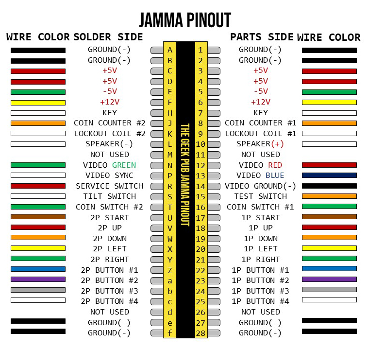
You can grab the JAMMA Pinout PDF here.
JAMMA Functional Diagram
Next up is the functional diagram for wiring up and connecting JAMMA boards and connectors. When wiring up a JAMMA we recommend the following order of operations:
- Connect AC1 and AC2 to the power supply and plug it into the wall.
- Test the 5V output with a multimeter and make sure it is close to 5V (between 4.8V and 5.1V is ideal).
- Disconnect the power and connect the +/-5V and 12V connections.
- Re-connect the power and test the 5V output with a multimeter. If it is not between 4.8V and 5.1V turn the +5V adjust until it is.
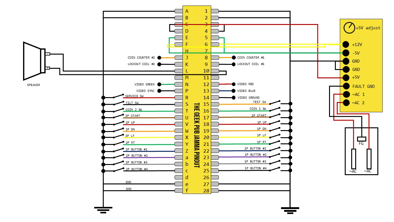
Again, just another reminder that not all arcade cabinets and games have all the same needs for connections. If your game only has 2 buttons, then button 3 and 4 will be missing.
You can grab the JAMMA Functional Diagram PDF here.
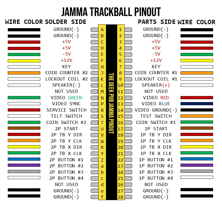
JAMMA Trackball Pinout
The JAMMA trackball pinout is slightly different from the JAMMA standard pinout as it replaces the joystick pins with the direction and clock pins from the track ball.