Blog
How Rotary Encoders Work – Electronics Basics
In this tutorial, we’re going to learn how rotary encoders work! Rotary encoders (also shaft encoders) are a fantastic way to dial in a position, or determine the position of a shaft. This could be the position of a knob you are turning, or it could be an encoder connected to a stepper motor to allow you to determine the position it is currently in. Rotary encoders are routinely used in electronics projects (and thus Arduino projects).
Overview of Rotary Encoders
A rotary encoder at its most basic description is an electro-mechanical device that converts the angular position and/or motion of a shaft (or axle) to an analog or digital output signal.
That’s a lot of technical jargon indeed and we’re going to break it down to three simple concepts. A rotary encoder allows your project to determine three specific things about a shaft or axle:
- It’s position, specifically its angular position
- The direction is it turning (i.e. clockwise, counter clockwise)
- The velocity (speed) at which it is turning (or if it is stationary)
Let’s break each of these down so we can understand them better.
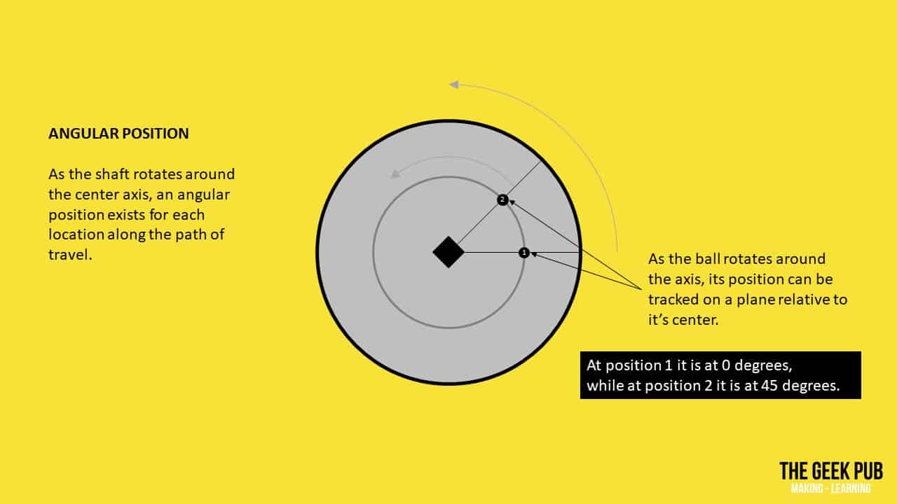
Angular Position
When objects rotate around an axis such as a shaft or axle, each point of the object follows a circular arc.
Direction
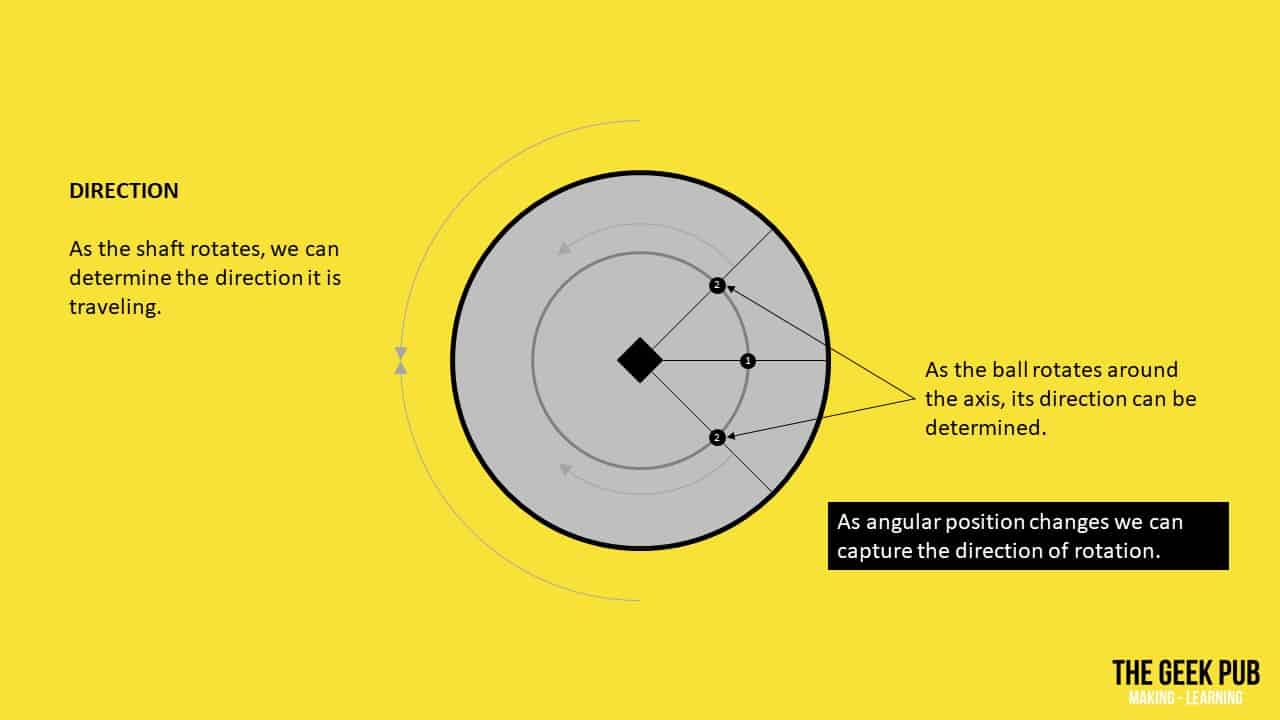
The direction that the shaft is turning, either clockwise or counter-clockwise can be captured.
Velocity
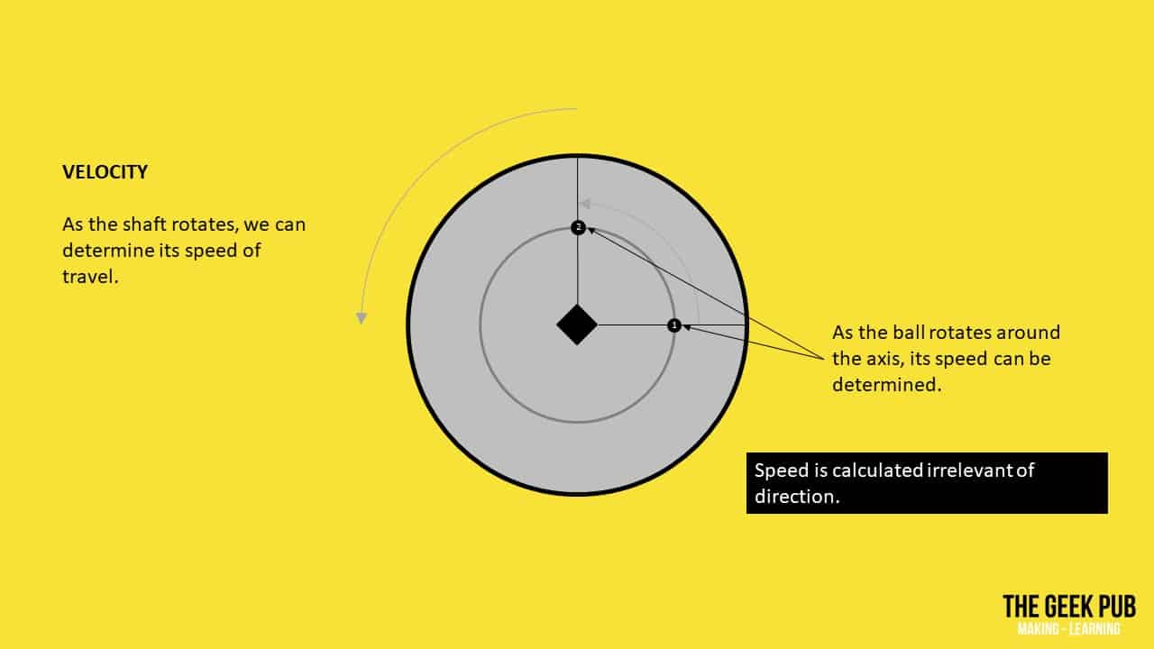
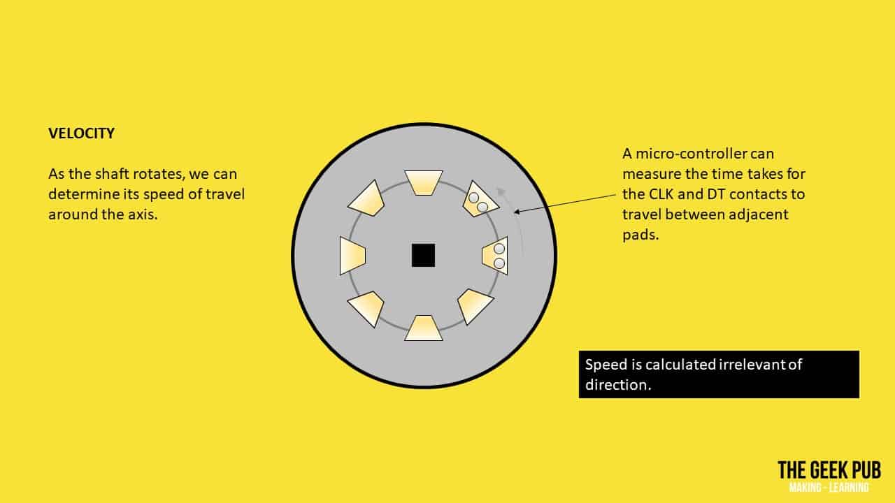
Finally, in addition to the position and the direction, we can determine the speed at which the shaft is turning.
Parts List for this Project
Here’s a handy parts list for this project to get you started:
- Arduino Uno
- Arduino power supply
- Breadboard and wires kit
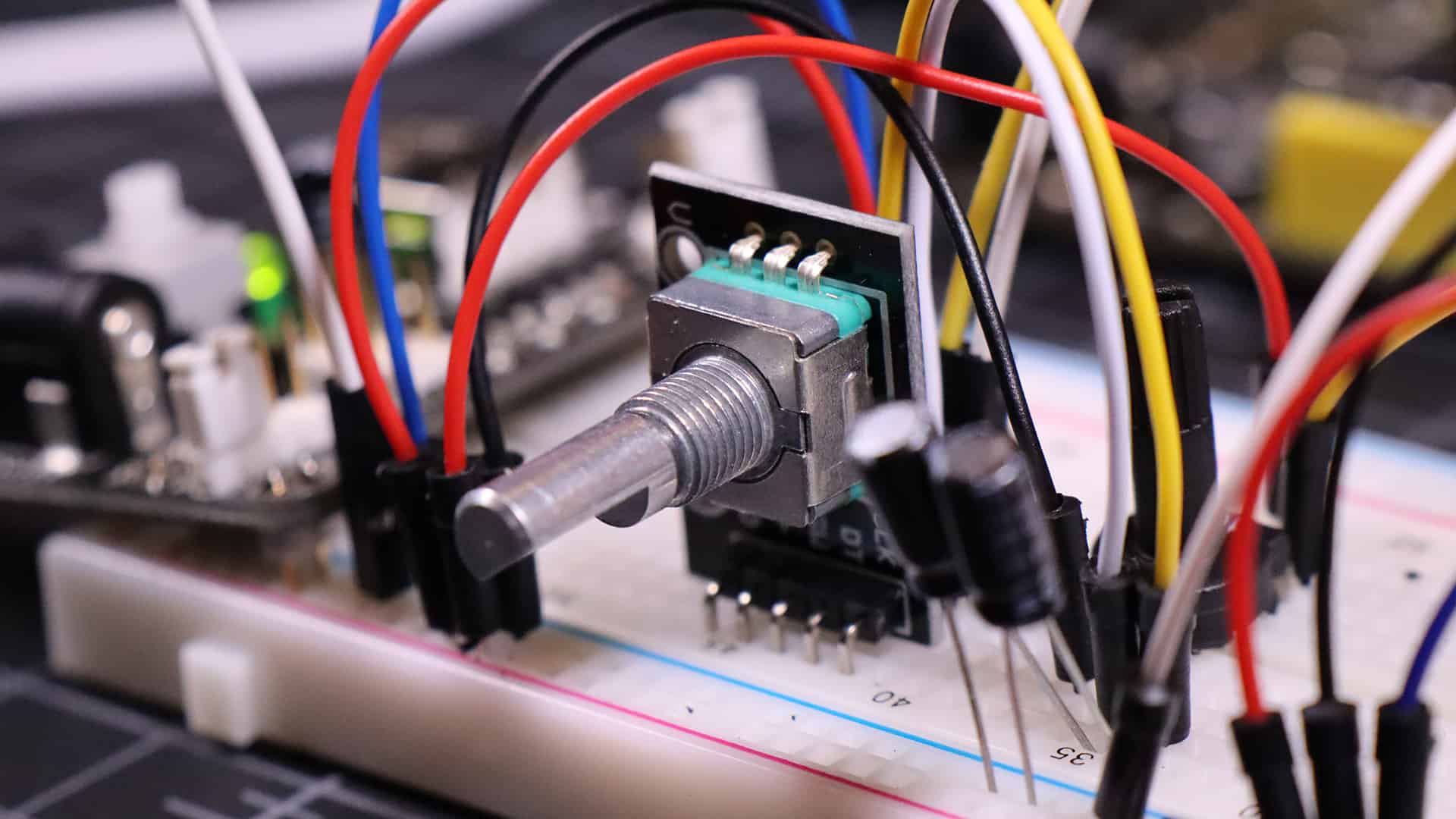
- Rotary encoder module
- 1µF electrolytic capacitor
- Character LCD display
- 10k potentiometer
How Rotary Encoders Work
So let’s move on and learn how rotary encoders work, or how they capture position, direction, and speed data. It’s quite simple, and utterly fascinating at the same time.
Absolute vs. Incremental Rotary Encoders
There are two general types of rotary encoders most commonly found in electronics projects. They are absolute and incremental rotary encoders.
- Absolute – With absolute rotary encoders the current position is always known as soon as power is applied. The are more costly to manufacture.
- Incremental – The most common is the incremental rotary encoder. These encoders are always in one of four electrical positions, and therefore require a calibration or homing operation to determine their starting location. Or in the case of many projects when power is applied a zero position is simply assumed (You’ll see this method in our counter example). They instantly report speed and direction, but do not keep track of absolute position.
As the incremental rotary encoder will be the most common type, we’re going to stick with those in this tutorial, but we wanted you to be aware that there is another type.
Rotary Encoder Mechanical and Electrical Construction
Inside a rotary encoder is a disc containing several electrical pads around its outermost region. The number of these pads will vary by encoder and brand, but ultimately determines how accurate it is. Above these pads are two contacts placed a specific distance apart. These contact are the clock and data lines.
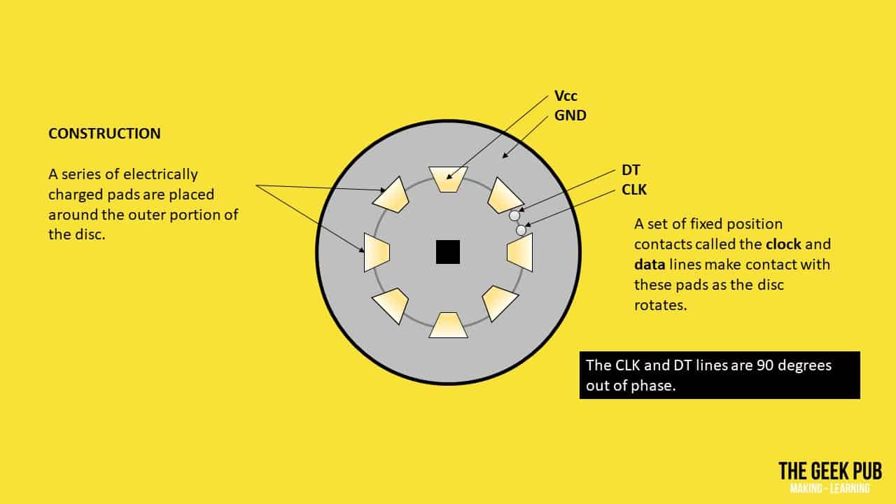
As the shaft of the encoder is rotated, the electrically charged pads will make and electrical connection with the clock and data lines contacts. This will create a two trains of electrical pulses that the electronics or micro-controller (ie. an Arduino, or
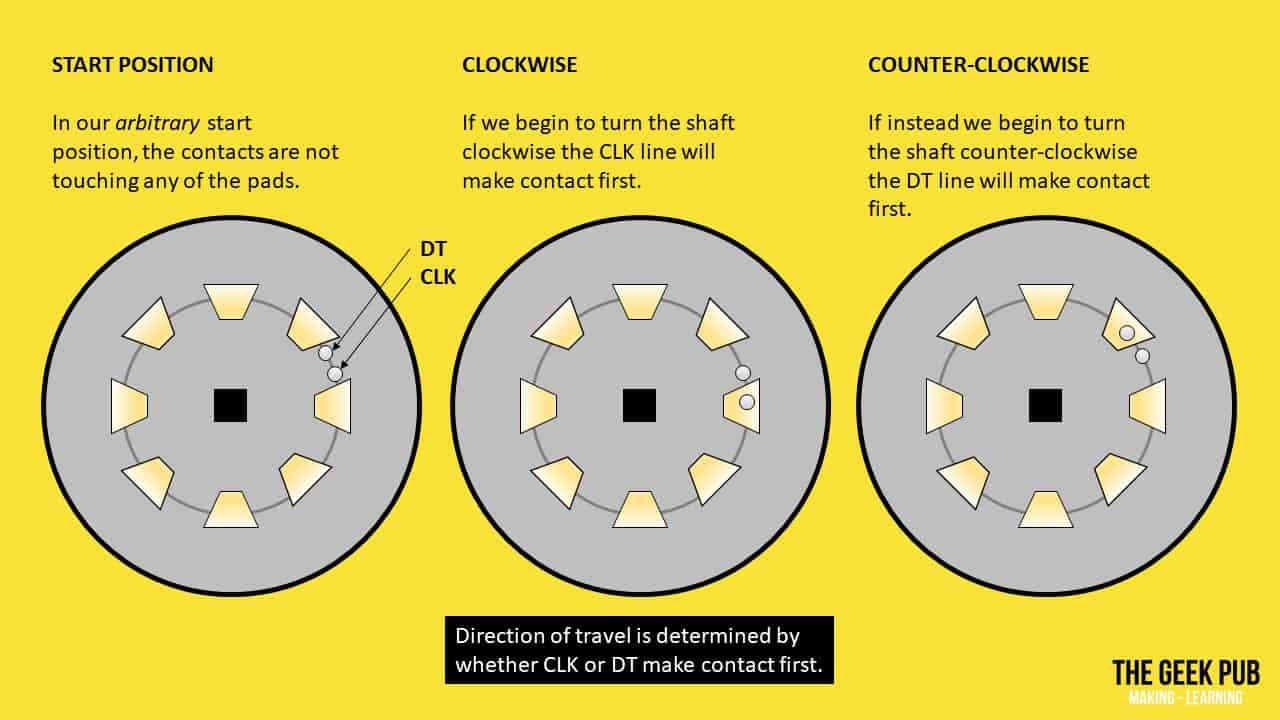
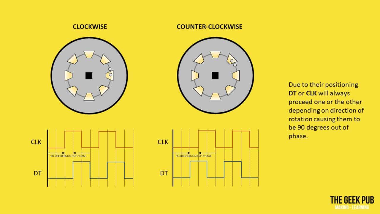
Due to the positioning of the clock and data line’s contacts, either the clock or the data line will make contact with one of the electrical pads first. If the shaft is turned clockwise, the data line will make contact first. If the shaft is turned counter-clockwise, the clock line will make contact first. This is how rotary encoders work to determine direction of travel!
Likewise, should the pulses reverse the phase will be out 90 degrees in the opposite direction. From this we can determine the shaft is now rotating opposite of its last known position.
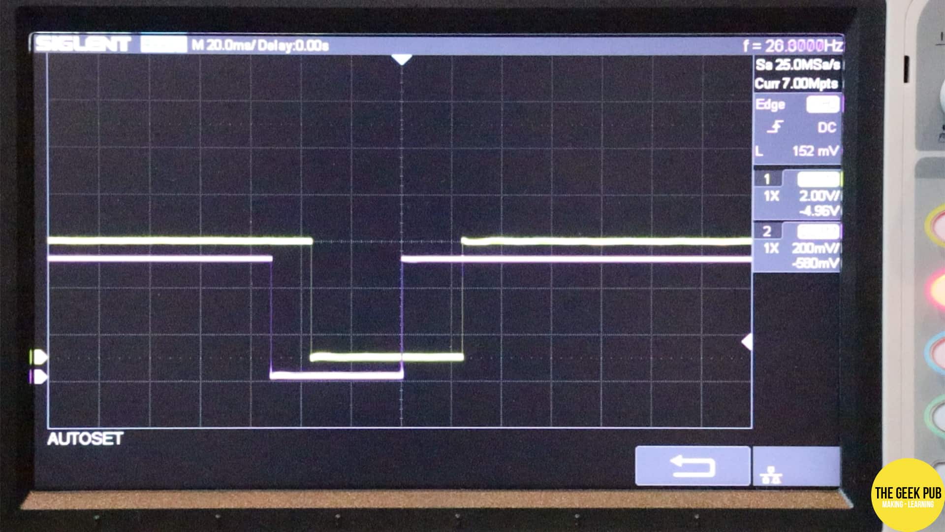
You can actually see this phasing difference if you connect a rotary encoder’s clock and data lines to your oscilloscope probes and turn the encoder’s shaft! You’ll need a two channel scope (most are). All you need to do is to connect the rotary encoder’s VCC and GND to +5 volt and ground respectively. Connect DT to channel 1, and CLK to channel 2. Connect both ground leads of the scope to the same ground as your rotary encoder.
RELATED: How Oscilloscopes Work
You can see the rotary encoder’s output here on my oscilloscope:
Lastly, using the same principles from above, your micro controller can time how long it takes for the clock and/or data line to pass from one pad to the next. From this it can determine simple how fast the rotary encoder is turning!
Using a Rotary Encoder for Counting Numbers
As we continue to learn how rotary encoders work, let’s look at a real world example that we can use in our projects. In this example, we will increment and decrement a a number on an LCD screen using the encoder! Turning the encoder clockwise will increment the number, while turning it counter clockwise will decrement the number.
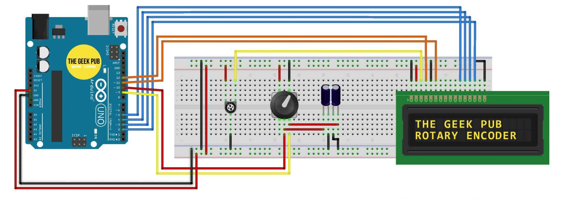
Wiring up the Rotary Encoder and LCD
Follow this Fritzing style diagram to wire up your rotary encoder module to an Arduino Uno. Although not completely necessary, I recommend adding two 1µF capacitors to your project. Connected to the CLK and DT lines. This will help debounce some cheap rotary encoders.
 Code for the Rotary Encoder Counter

Pop the following sketch into your Arduino IDE and upload it to your Arduino Uno.
[code language=”cpp”]
#include <LiquidCrystal.h> //Default Arduino LCD Librarey is included
// encoder CLK and DT pins
int EncoderCLK = 10;
int EncoderDT = 9;
// counter variables
int Previous_Output;
int Encoder_Count;
// Setup LCD Pins
const int rs = 12;
const int en = 11;
const int d4 = 5;
const int d5 = 4;
const int d6 = 3;
const int d7 = 2;
LiquidCrystal lcd(rs, en, d4, d5, d6, d7);
void setup() {
lcd.begin(16, 2); //Initialise 16*2 LCD
lcd.print(" THE GEEK PUB "); //Intro Message line 1
lcd.setCursor(0, 1);
lcd.print(" ROTORAY ENCODER "); //Intro Message line 2
// wait 2 seconds before begining and clear intro message
delay(2000);
lcd.clear();
//pin Mode declaration
pinMode (EncoderCLK, INPUT);
pinMode (EncoderDT, INPUT);
Previous_Output = digitalRead(EncoderCLK); //Read the inital value of the CLK line
}
void loop() {
if (digitalRead(EncoderCLK) != Previous_Output)
{
if (digitalRead(EncoderDT) != Previous_Output)
{
Encoder_Count ++;
lcd.clear();
lcd.print(Encoder_Count);
lcd.setCursor(0, 1);
lcd.print("CLOCKWISE");
}
else
{
Encoder_Count–;
lcd.clear();
lcd.print(Encoder_Count);
lcd.setCursor(0, 1);
lcd.print("COUNTER-CLOCKWISE");
}
}
Previous_Output = digitalRead(EncoderCLK);
}
[/code]
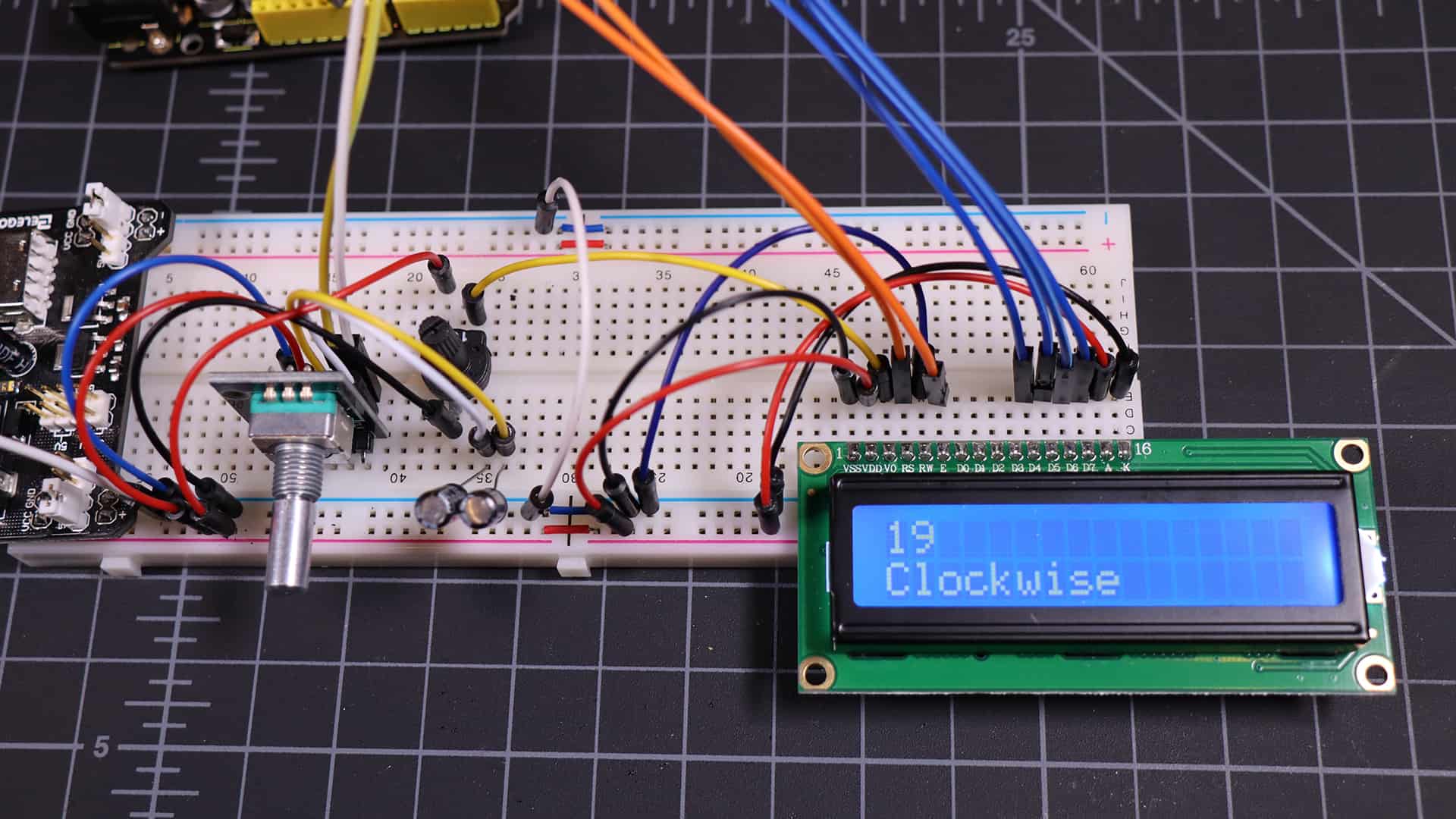
Completed Rotary Encoder with LCD Screen
With the project completed, you’re now ready to count numbers on your LCD display! Turning the rotary encoder clockwise and counter clockwise should count numbers up or down! Now you know how rotary encoders work!
Debouncing Rotary Encoders
Sometimes, especially with cheaper rotary encoders, this code and wiring style will result in an encoder that “bounces.” This is the same type of bounce problem you might find with a momentary push-button switch. If you experience your counter jumping past numbers, such as skipping from 5 straight to 8 for example then you’ve got a bounce problem.
If you run into this, the first thing to try is using 1µF capacitors connected to the CLK and DT lines (and to ground). This has worked for me roughly 90% of the time. If that doesn’t work you’ll want to look into debouncing in code, which is out of scope for this tutorial. We hope to do a debouncing tutorial in the future and will link to it from here.
Another option may be to simply buy a higher quality encoder.


4.5
I can’t wait for your debouncing tutorial! This is a problem that has plagued me with these cheap encoders.
Thanks! I hope to do one soon!
4.5
Yeah, I have had lots of bounce problems with these encoders. And to be honest, I don’t really understand bounce in the first place. So I’d def enjoy a tutorial on that.
Thank you for this! Saved me a lot of trouble.
3.5