Blog
Bridge Rectifier Circuit – Electronics Basics
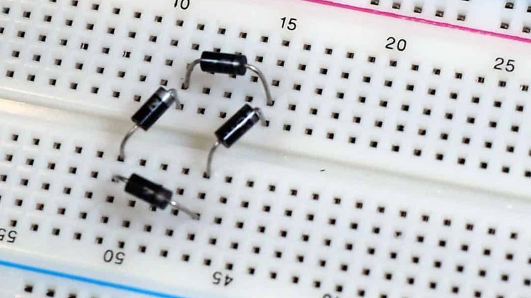
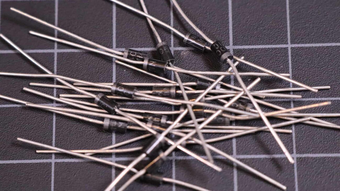
In this tutorial, it’s going to be all about rectifiers! We’re going to learn the basics of their operation, and then we’re going to build a bridge rectifier circuit out of four diodes that can be used in your projects to convert AC to DC.
In a previous tutorial we talked about diodes and how they work to control the direction that current can flow in a circuit. Then we built on that knowledge to create a USB charger circuit that can be used to power standard USB devices by converting 120V AC (or 220V AC) down to a regulated 5V DC.
Let’s take it a step further and lean about the different types of rectifiers and how you might use them in your projects.
What is a Bridge Rectifier?
The textbook definition is that a “diode bridge” consists of four diodes in a bridge circuit configuration that provides the same polarity of output for either polarity of input. Another way to put it would be that a ridge rectifier converts alternating current (AC) to direct current (DC). Bridge rectifiers are commonly used in power supplies to convert mains electricity from your wall outlet to DC electricity that can be used by home electronics devices like your stereo, computer, or TV.
Of course, that’s not all that easy to understand for beginners. We’re going break this down in just a bit so we can really understand what’s going on here, but before we do let’s go over the basic types of rectifier circuits.
Types of Bridge Rectifiers
Bridge rectifiers can be categorized into several different types based on some simple criteria, but the main categories we will cover is single phase rectifiers, three phase rectifiers, controlled rectifiers, and uncontrolled rectifiers. Some of these categories can be combined. For example you could have an uncontrolled single phase rectifier.
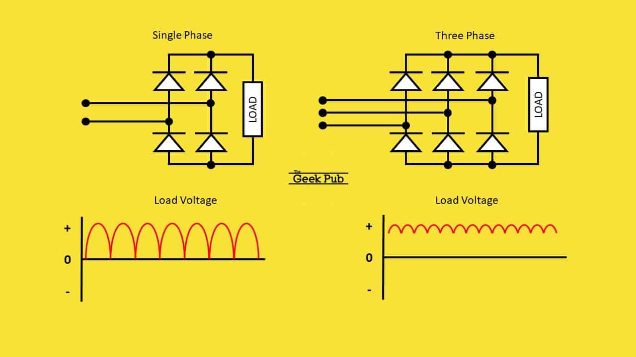
Single Phase and Three Phase Rectifiers
As me move forward with our bridge rectifier circuit tutorial, we can break most rectifiers down into two categories, single phase or triple phase. The decision on which circuit to go with is as simple as determining the supply. If you’re working with single phase inputs (most of the time) you’ll use a single phase rectifier. In many industrial environments, three phase supplies are common and you’ll need to use a three phase rectifier.
Regardless of phase, a bridge rectifier can be controlled or uncontrolled.
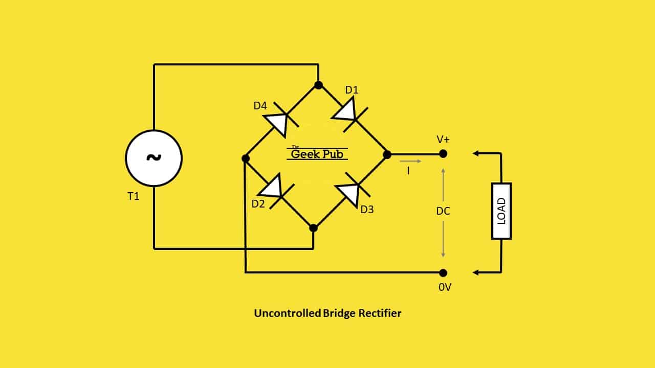
Uncontrolled Bridge Rectifiers
Uncontrolled bridge rectifiers are the most common type you’ll find in electronics and power supplies. These are based solely on diodes, and do not use any additional components for regulating the voltage or current. These types of circuits are generally found in fixed power supplies. Simply put, the input voltage is uncontrolled as it passed through to the output side. If 12V enters the circuit, ~12V rectified exits the circuit.
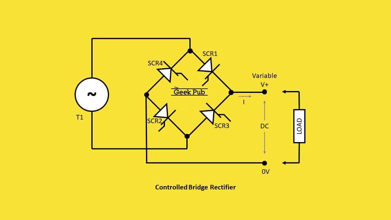
Controlled Bridge Rectifiers
In a controlled bridge rectifier, diodes are replaced with solid state components such a silicon controlled rectifiers (SCR), or thyristors. These devices are able to vary the output voltage. This can be very handy for use in variable power supplies that need to adapt to different loads.
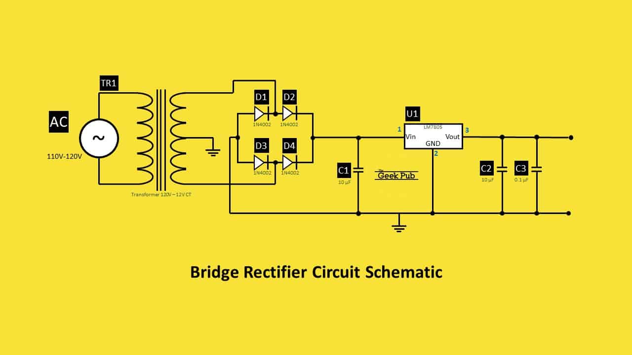
Bridge Rectifier Circuit Schematic and Diagram
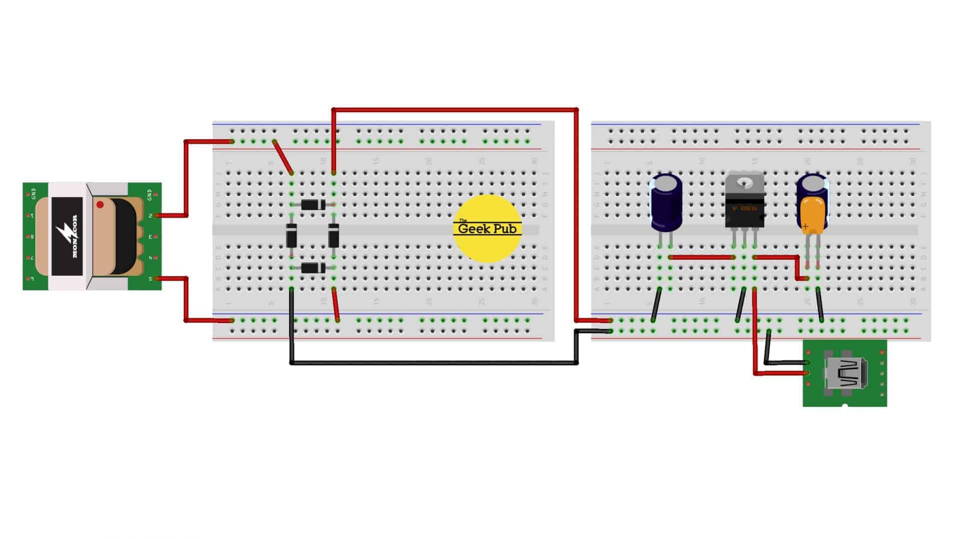
Building a useful bridge rectifier circuit is a piece of cake one you know the basics. To get the full benefit of a bridge rectifier, you’ll need to add some additional components. We highly recommend checking out our USB charger circuit tutorial as it covers all of the basics of how this completed circuit works.
How Bridge Rectifiers Work
As I mentioned at the beginning of this bridge rectifier circuit tutorial, we’re going to explain how they actually work. Something that every electronics hobbyist should do. As mentioned in the video, you can buy bridge rectifiers but you should make your own at least once because its a fantastic learning opportunity!
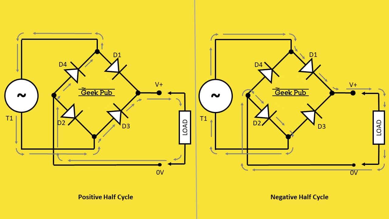
For the purpose of explaining how bridge rectifiers work, we’re going to focus on single phase rectifiers to keep things simple. A single phase bridge rectifier works by placing four diodes across a load.
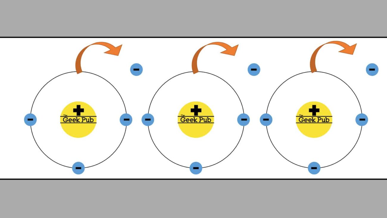
On the positive half cycle of the AC current diodes D3 and D4 are forward biased (current is flowing), whole diodes D1 and D2 are reverse biased (current is blocked). On the negative half cycle D1 and D2 become forward biased, while D3 and D4 become reverse biased, exactly the opposite.
What this translates to is that current at the load is always traveling in the same direction. If you’re still not sure how it works, remember that diodes only allow current to travel in a single direction.
RELATED: How Diodes Work
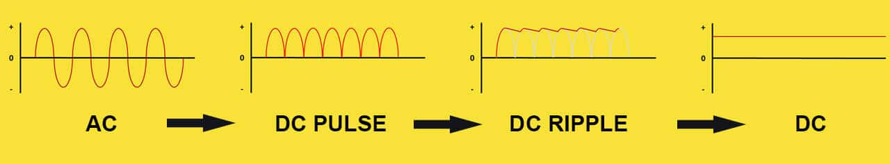
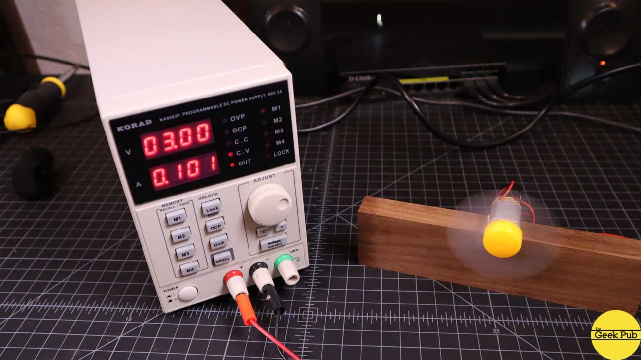
Now, a bridge rectifier on its own doesn’t truly convert AC as we found out in the USB charger circuit demo. It only converts AC into a DC wave pulse (or DC oscillation). It requires some capacitors to clean up the pulse and create a more DC like signal. It’s also a great idea to put a voltage regulator in the circuit to clean things up and keep the voltage stable, even in the input voltage drifts up or down due to fluctuations in the grid.
So now you know how a bridge rectifier circuit can convert AC into DC with just a bit of careful planning in your circuit design!
0.5
4.5
5
Flippin fantastic article. This is quickly becoming my go to electronics site!
I always thought a full bridge rectifier actually made DC. I didn’t realize it needed smoothing capacitors!
1.5