Blog
Building a USB Charger Circuit
In this project we’re going to make a USB charger circuit from some simple parts we have lying around the house. A USB charger circuit ouputs a regulated 5V that can be used to power USB devices or even charge mobile phones and other devices.
We will step through this build in 4 phases of construction:
- Voltage Step Down – First thing we have to do is step the voltage down from 120 volts AC to something low enough we can work with. In our case we’re going to step down the voltage to 12 volts AC.
- Rectification – After stepping down the voltage to 12 volts AC, we need to convert it to DC or direct current. We will do that by building a super simple full wave bridge rectifier circuit.
- Filtration – We want to make sure this circuit is stable and not producing ripple. We will add some capacitors to solve this problem.
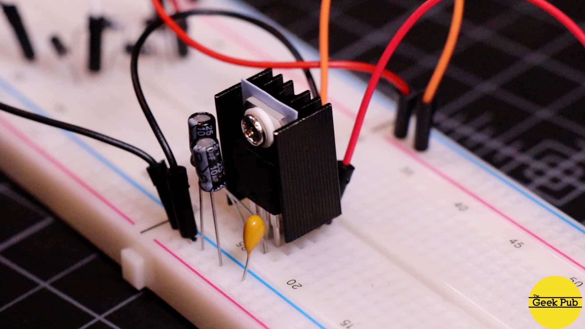
- Voltage Regulation – Finally, we want to ensure our circuit outputs a consistent voltage, even if the power from the mains is not stable. Additionally, we need to step down our voltage from 12V to 5V. We will do that with a LM7805 voltage regulator and heatsink.
If you’re new to electronics we have a ton of resources to help you get started. As we go through this tutorial we will link quite a few additional resources in case you need some help. You might start with our tutorial called “What is voltage?” Another great way to step down voltage for small loads is to use a voltage divider.
RELATED: Voltage Divider Calculator
Parts List for this Project
Here’s a han dy parts list for this project to get you started:
- 120V to 12V step-down transformer
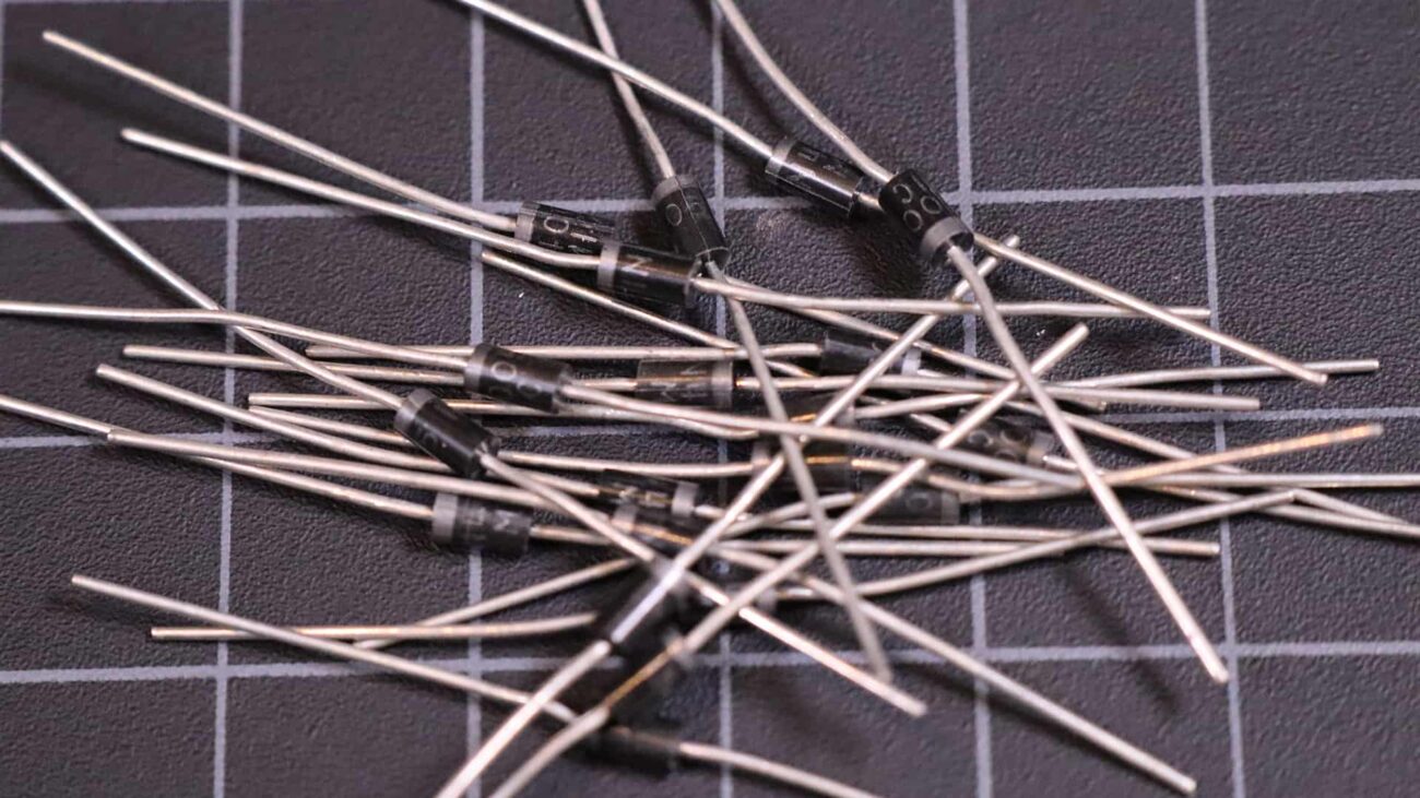
- 1N4002 rectifier diodes
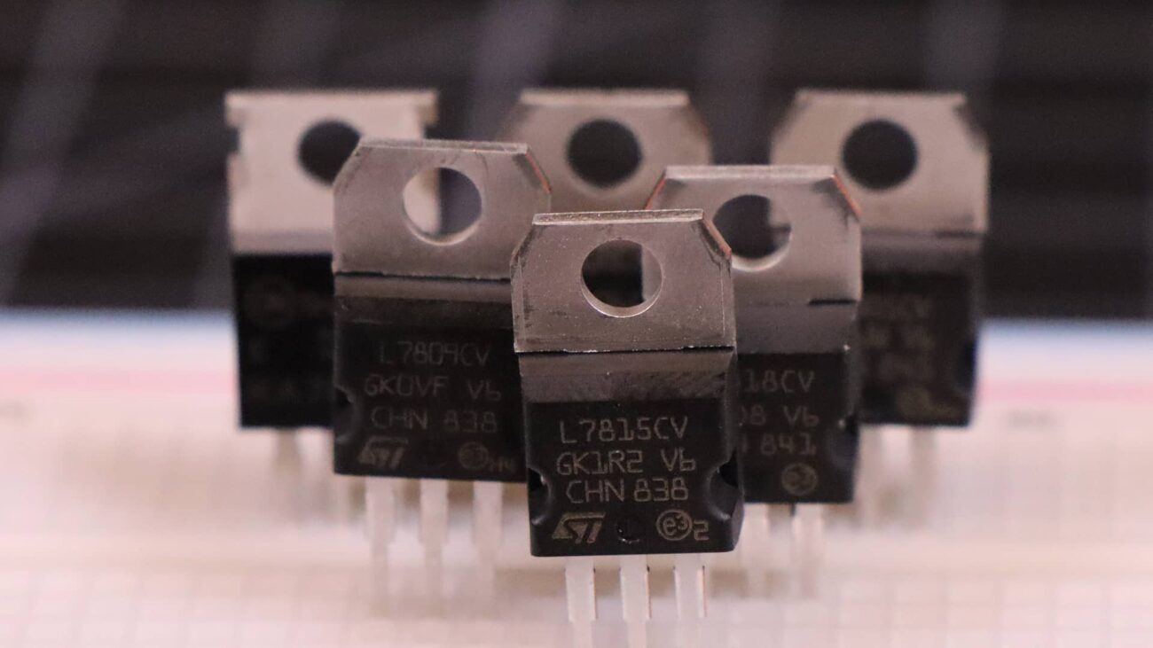
- LM7805 voltage regulator
- Heatsinks for regulator
- 10uF electrolytic capacitor (x2)
- .1uF ceramic capacitor
- Breadboard
- Breadboard wires
- USB cable
You might also be interested in our guide to buying your first multimeter, and picking an oscilloscope.
Another thing you might want to consider, depending on the nature of your project is that there are more efficient circuit designs out there for USB charger circuits that utilize semiconductors and switching. I chose not to use those for this project because 1) I didn’t have any in my parts bin, and 2) it would be much harder to understand. This tutorial is about learning the basics of how this stuff works.
USB Charger Circuit Tutorial Video
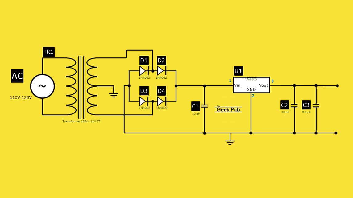
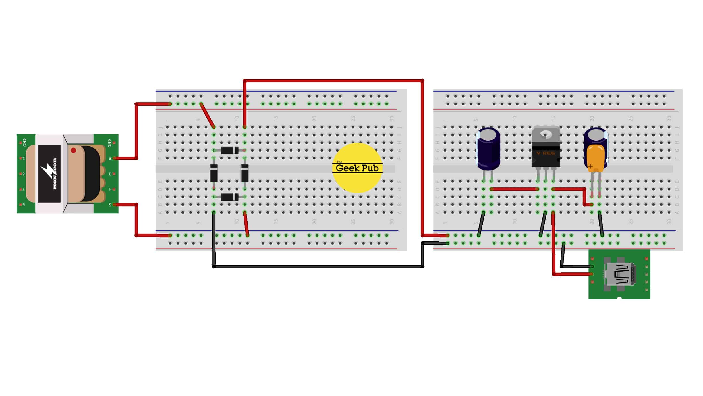
The Schematic and Diagram
The following is a schematic and Fritzing style wiring diagram that should help you build this circuit.
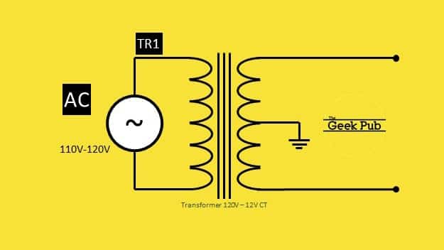
Stepping Down the Voltage
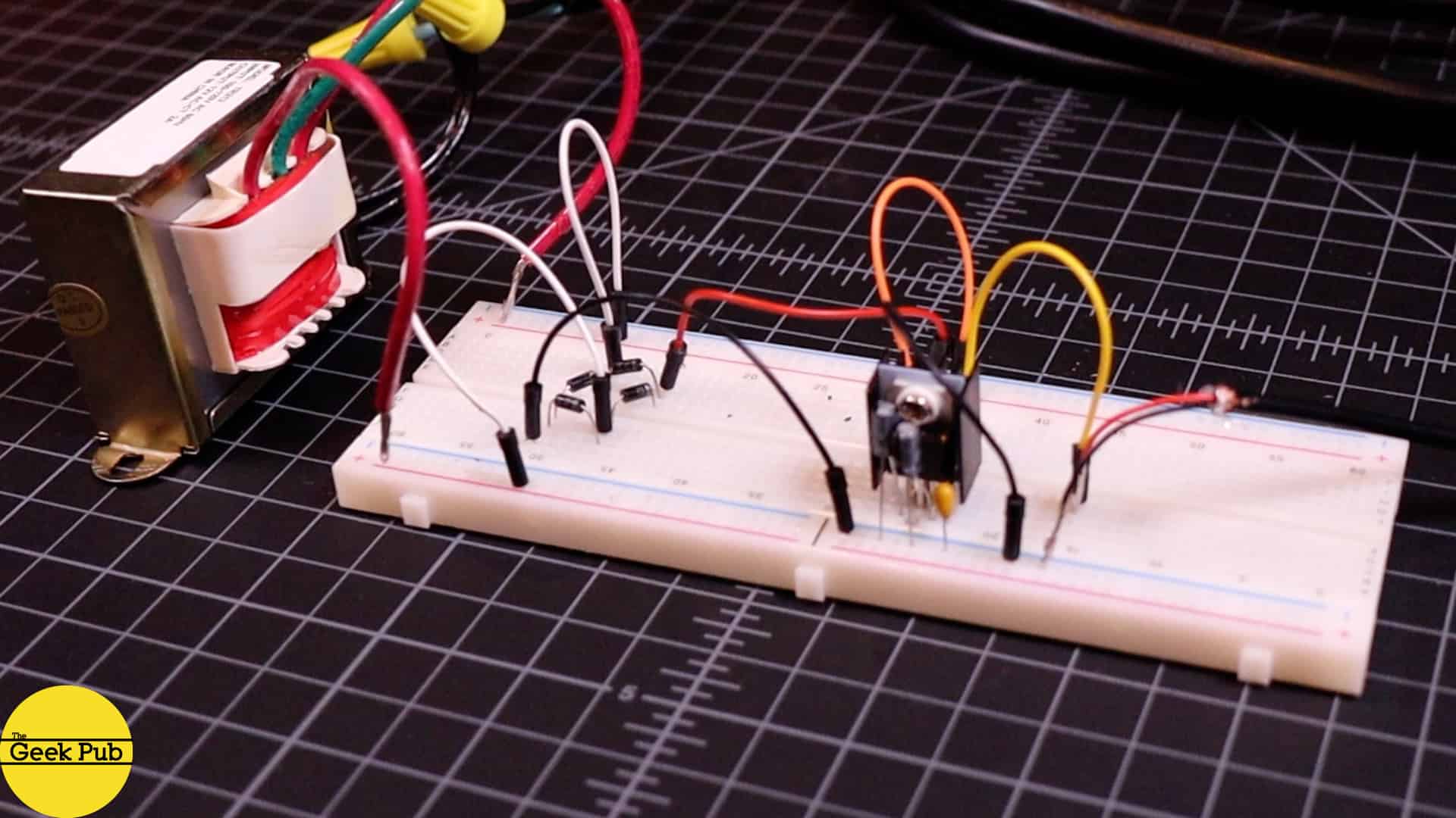
The first thing we need to do is to convert our wall outlet, or mains voltage down to something that is both safe for us humans and something that in a range that our components can work with. This will require a step-down transformer. The one we’re going to use converts 120V AC down to 12V AC. If you live in other countries where the standard voltage is 220V AC, the only thing in this project you’ll need to change is the transformer.
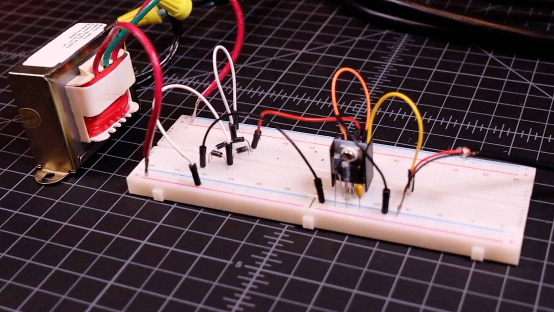
I used this 120V to 12V transformer that I had laying in my parts bin. Its capable of up to 2 amps.
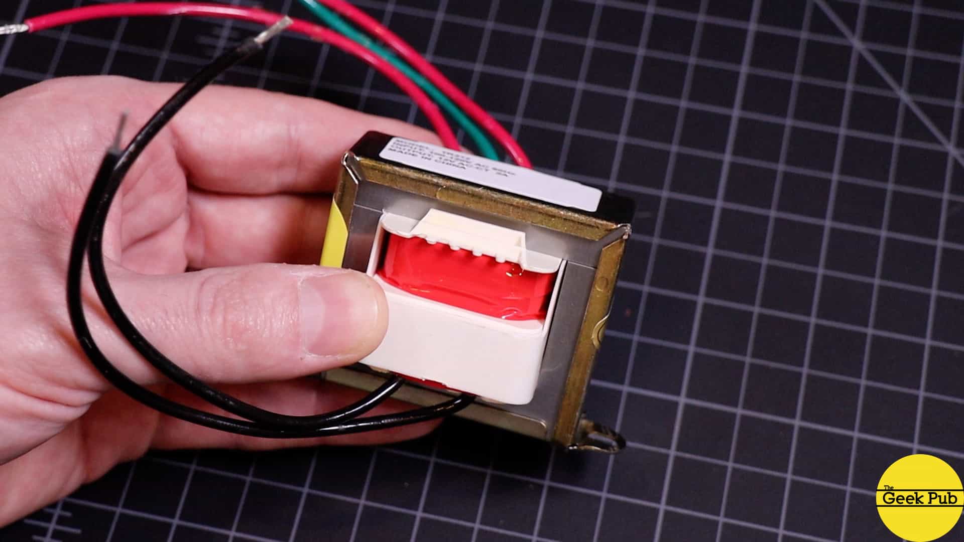
One thing to note, you could also used a 120V to 24V transformer, or a 120V to 9V transformer. The important part is to make sure you voltage regulators input side can work with whatever your input voltage is. In my case, I am using an LM7805 that supports an input voltage of 8V to 25V.
The closer you can be to that lower number the more efficient your circuit will be.
Rectification
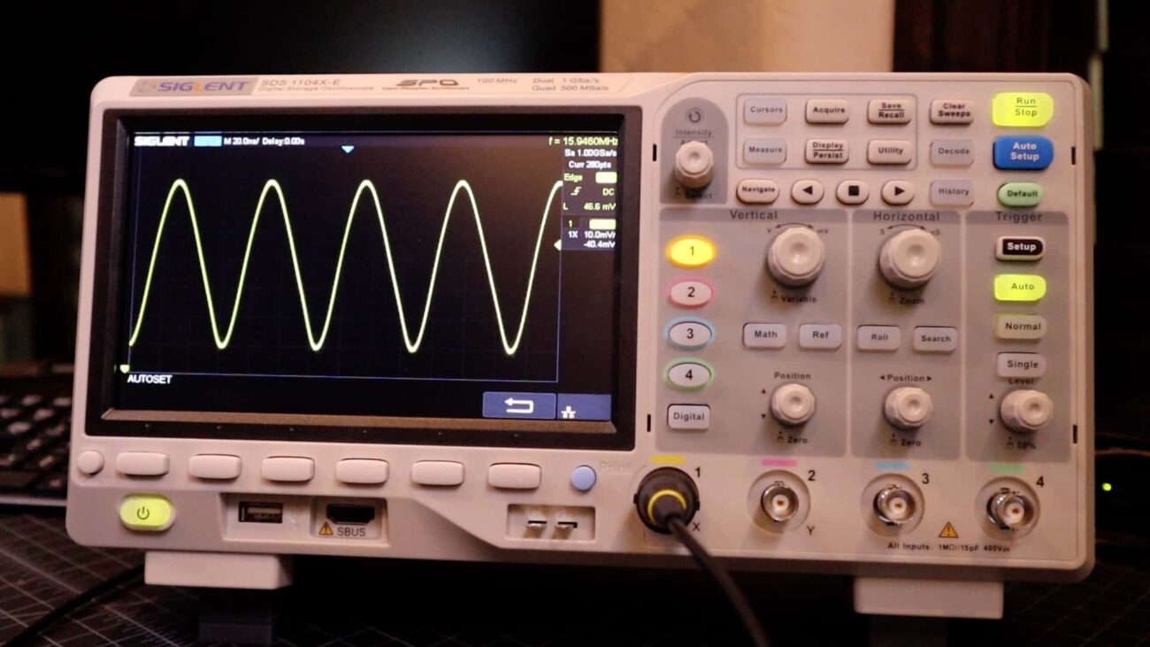
After stepping down the voltage to 12V we’re in good territory, but we’re still AC. Our USB charger circuit needs to be DC! To do that we’re going build a full wave bridge rectifier circuit.
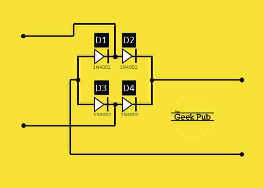
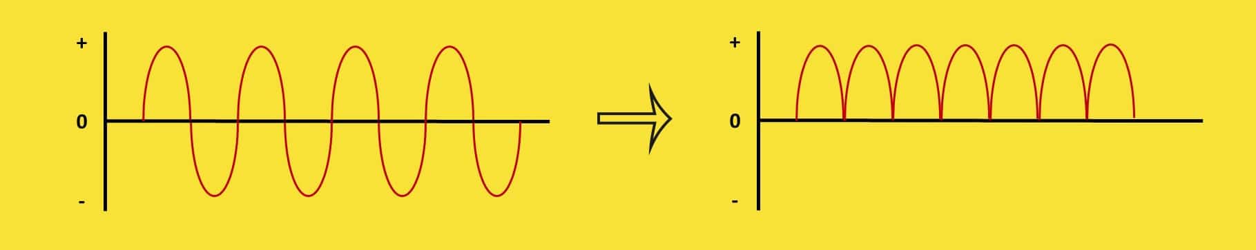
Rectification removes the negative portion of the AC waveform. A full wave bridge rectifier circuit is built using four diodes. As you know, diodes only allow current to flow in one direction. In first half cycle of the AC waveform, diodes D2 and D3 are forward biased whole diodes D1 and D4 are reversed biased. In the second half cycle of the AC waveform, diodes D1 and D4 are forward biased, while diodes D2 and D3 are reversed biased.
Simply put, what happens during this process is that the negative portion of the waveform is converted to positive!
RELATED: How Diodes Work
However, at the end of the day, this still isn’t a DC circuit and not clean enough to feed to our USB devices. We need to do a couple more things.
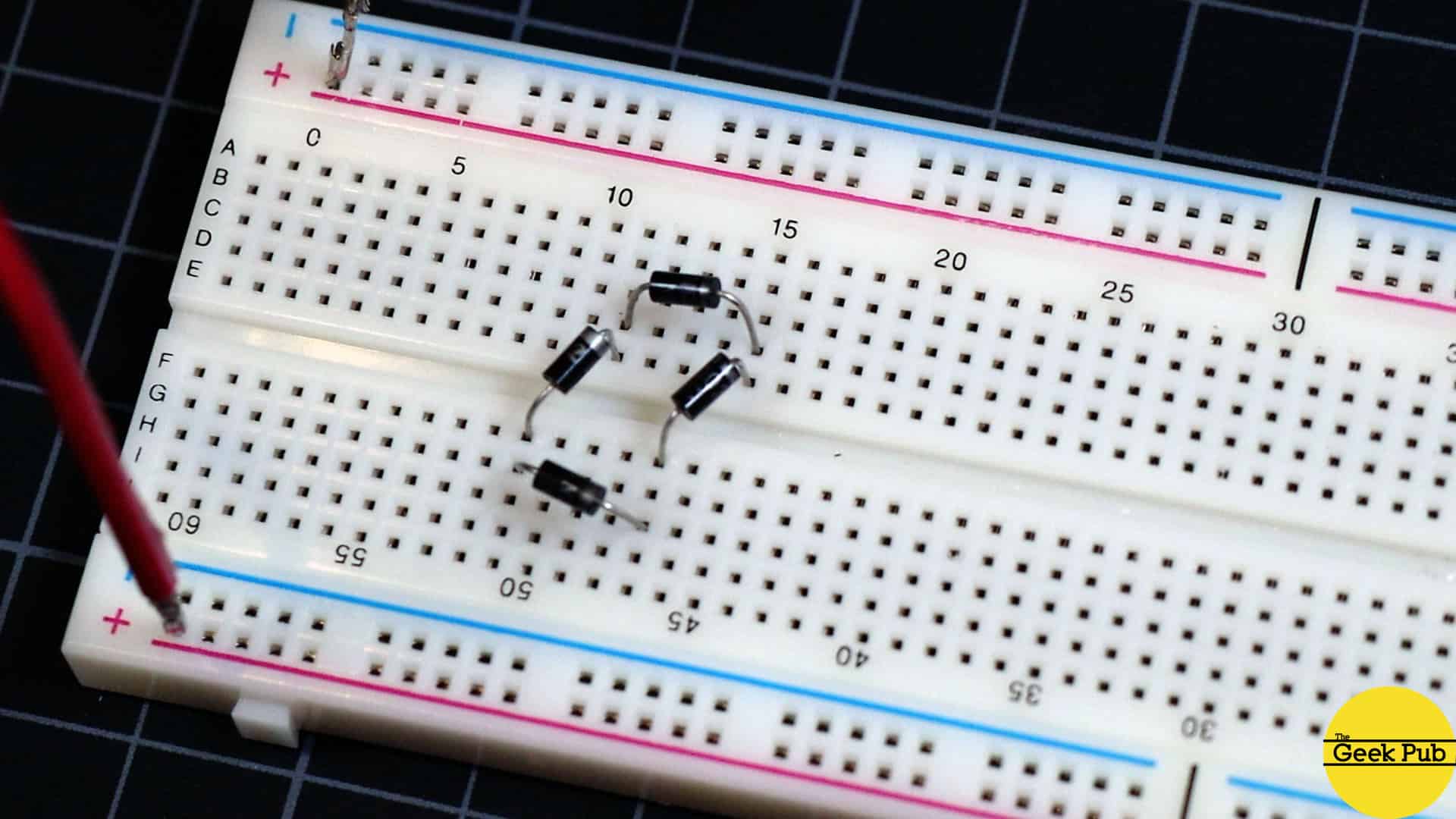
One additional note before we move on. You can buy off the shelf bridge rectifiers. But I think its important for everyone to build their own at least once so they can learn how they work. The off the shelf rectifiers are ultimately nothing but diodes in a single package.
Filtration
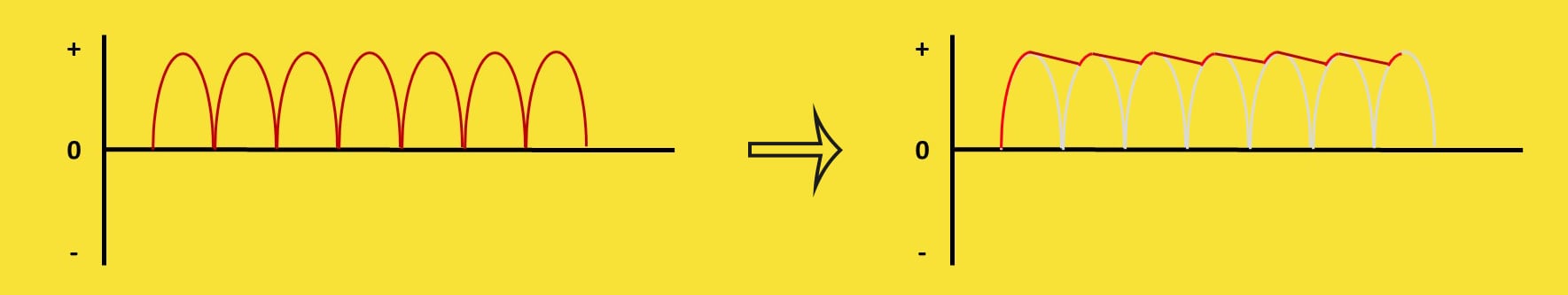
We need to get this waveform flattened into a true DC as we’re still not quite in true DC territory yet with all of this ripple in our waveform.
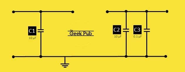
We will solve this by adding filter capacitors to the circuit. These filter caps will go on both sides of a voltage regulator. They will charge until the oscillation reaches its peak, and then as the oscillations fall low, the capacitors will discharge into the circuit flattening out the oscillations and creating DC.
It’s a very simple fix.
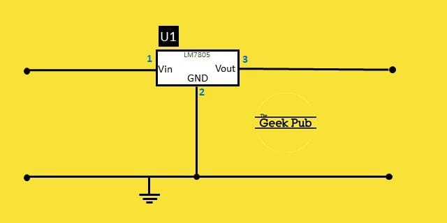
Voltage Regulation
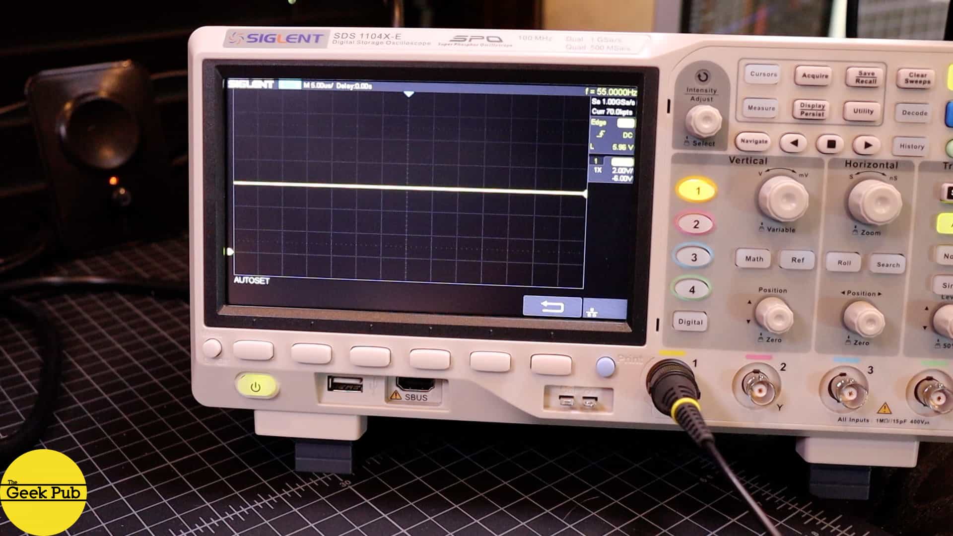
We’re almost finished building our USB charger circuit! The last thing we need to do is add a voltage regulator to keep the voltage stable at 5V for our USB devices to consume.
Without voltage regulation, our 5V could rise up or fall down as the AC input changes. This could happen if there was a power spike or a brown out. That could have disastrous effects on the device we intent to power.
RELATED: How Voltage Regulators Work
The voltage regulator also solves another problem for us. It lowers the 12 volts we’re getting from the transformer down to 5 volts. Voltage regulators can generally handle a wide range of varying input voltages. The LM7805 that I chose can handle anywhere from 8 volts to 25 volts on the input side. The closer your transformer’s output to lower number on your regulator, the better the efficiency will be and the less heat the voltage regulator will produce.
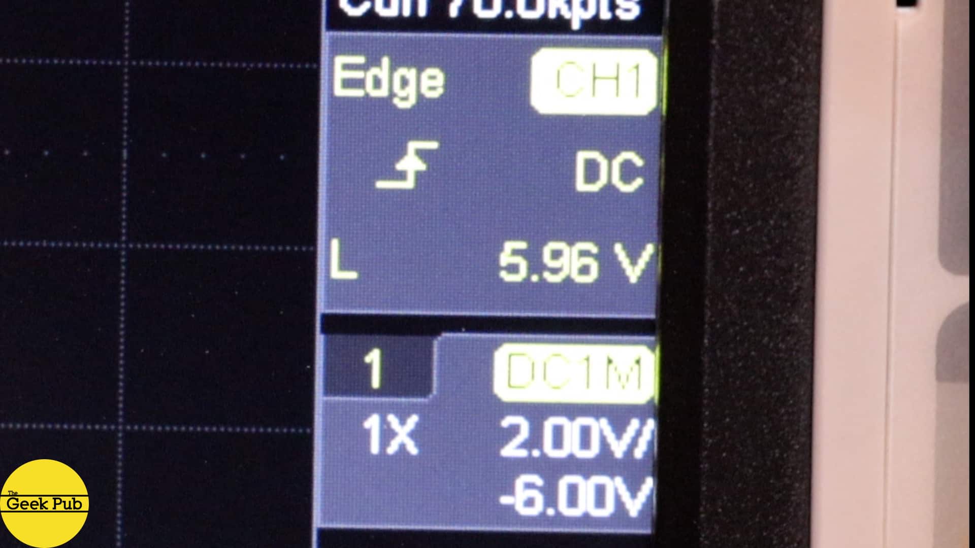
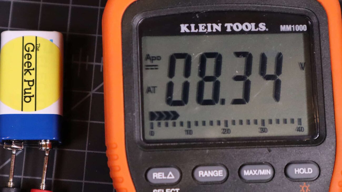
As you can see now on the oscilloscope, we have a perfectly stable 5 volts for our devices to consume (5.96 without any load on the circuit is normal).
RELATED: Oscilloscope Tutorial
Some Final Thoughts on this USB Charger Circuit
There are some final thoughts I’d like to share with you about this USB charger circuit and its design.
It is not the most efficient design for a USB charger! Yep. That’s right. There are far more efficient designs that use semiconductors and switching techniques. However, those circuits are almost like magic and they don’t serve the purpose of teaching very well. The entire purpose of this circuit tutorial was to show the steps you need to go through to convert mains AC down to a regulated 5 volts that a USB device can consume. Showing a a chip with two wires in and two out doesn’t teach much.


4.5
I built a very similar circuit to this when I built my Geek Pub arcade because I didn’t want to use a USB charger like you did.
Thanks Mike, that’s very nicely explained
Very nicely done. I too built something like this USB charger circuit for a project where I needed to power a USB LED light strip. The only thing I would recommend is a bigger heat sink on the voltage regulator if you make this for permanent installation. I of course realize it doesn’t matter for this little prototype.
This is fantastic. Can you tell me what chip does all of this like you mention in the video?
4.5
0.5
@FFCK Google switching transformer.
Well I just learned a thing or two!
4
1.5