Blog
UART Communications Basics
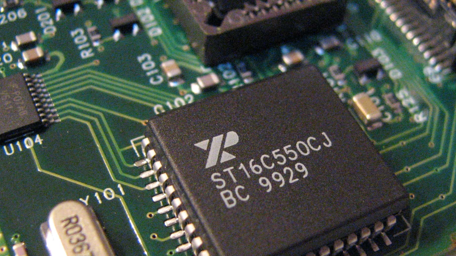
In this tutorial let’s talk about UART communications basics! A UART (short for Universal Asynchronous Receiver/Transmitter) is an electronic component that you’ll find in all sorts of electronics. UARTs have been around since the early days of PCs and were mostly associated with MODEMs of the time because a high quality MODEM would of course need a high quality UART. The UART could be a standalone integrated circuit, or included as part of a larger multi-function IC.
The Basics of UART Communications
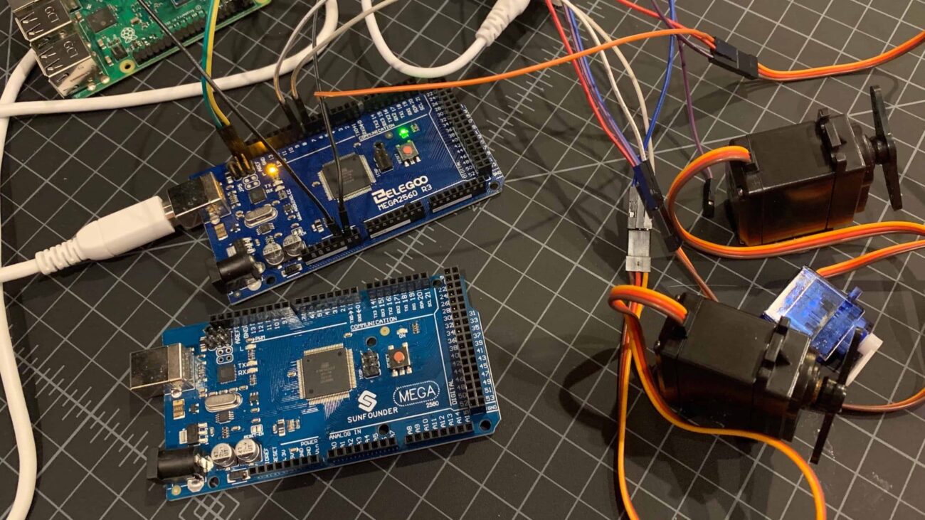
UARTs are still in use today in many types of electronics including the
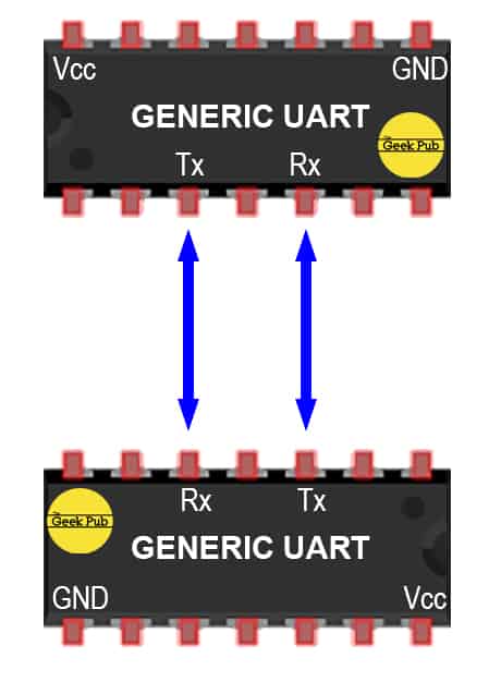 For UARTs to be of any value there must be two of them. UARTs talk to each other. They can be different types, one standalone and one integrated, etc. But for communications to happen they work in pairs. For the more advanced who will point this out, it is possible to emulate a UART in software using a CPU or a micro-controller . That’s beyond the scope of this article, as we’re focusing on UART communications basics here.
The UARTS communicate by connecting the Tx pin (transmit pin) of one UART to the Rx pin (receive pin) of the other UART (in both directions). This two wire loop forms the fundamental circuit that the UARTs operate on. (Depending on the actual use of the UART it my be wise for them to also have a shared ground.) Data flows from the transmit pin on one UART to the receive pin on the other.
UARTs and Baud Rate
If you’ve been around electronics for a while you might have heard of something called a baud rate. Since UARTs don’t use a clock line commonly used in other serial communications methods (such as I2C or SPI), it requires that both UARTs talk at the same speed. This also means that speed must be manually defined at both ends. This is why in the Arduino IDE’s serial monitor there is a drop down box to change the speed! Baud rate is measured in bits per second. Since not every chip is timed exactly UARTs allow for a 5% variation in baud rate by design. Anything deviation greater than this and data is likely to be corrupted in transit.
Once a baud rate is set on both ends the transmitting UART will send a start bit before beginning transmission and a stop bit at the end of the transmission.
How UARTs Work: The Basics
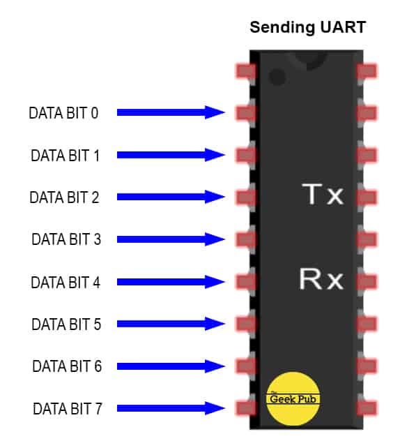
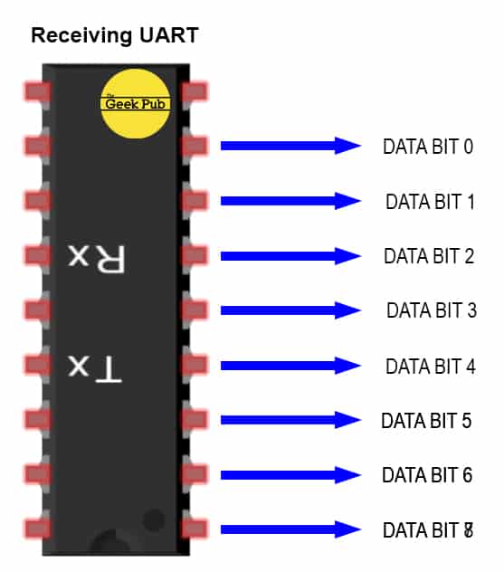
Our UART is going to receive data in parallel form on its bus pins. The UART will internally serialize this data set and transmit it as a packet bit by bit over its Tx pin. The second (or receiving) UART will read this packet on its Rx pin and then output the data on its data bus pins. Let’s go through the steps.
![]()
Understanding the UART Data Packet
It’s also important to understand that the serial portion of the transmission between the Tx pin and Rx pin as packetized into a standard format. This packet varies depending on the type and design of the UART, but will follow the same basic design. A single start bit, followed by 5 to 9 data bits. At the end may be a party bit, followed by 1 to 2 stop bits. Here’s a handy UART packet diagram.
![]()
Let’s break those down so quickly, so that we understand their importance.
START BIT
Much like other communications systems, there must be a mechanism for controlling the line and letting the receiving device know that a transmission is starting. The transmitting pin normally holds the line HIGH when idle. In order to indicate to the receiving UART that data is about to be sent, the transmitting UART pulls the line low for one clock cycle (based on the configured baud rate). This causes the receiving UART to start reading the bits of the data frame.
DATA FRAME
This is the actual data we’re transferring without any overhead. It can be variable length determined by if we’re using parity or not. Most UARTs send the least significant bit first, but this does vary some by design.
PARITY BIT(S)
Party is a way of determining if data has been transmitted accurately. More precisely, its describes if a number is even or odd. The UART will add all of the bits of the frame up and determine wither they add up to an even number or an odd number. The receiving UART will check the parity against the data it received. If they don’t match, it knows the data frame is corrupted. Not all UARTs use parity bits. Additionally, using a parity bit will make the data frame shorter by one bit in most designs.
STOP BIT(S)
In order to communicate to the receiving UART that transmission is complete, the sending UART will bring the line HIGH for one or two clock cycles.
How UARTs Work: Step-by-Step
As we continue down our UART basics tutorial, it’s time to go over the communication process step by step.
STEP 1: The sending UART receives a data frame from the data bus in parallel format and adds the start, parity, and stop bits to the data frame.
 STEP 2: Using the pre-configured baud rate, the transmitting UART pulse the transmit pin with high and low states. The receiving UART collects these bits, drops the start, parity (if any), and stop bits from the packet, leaving only the data frame.
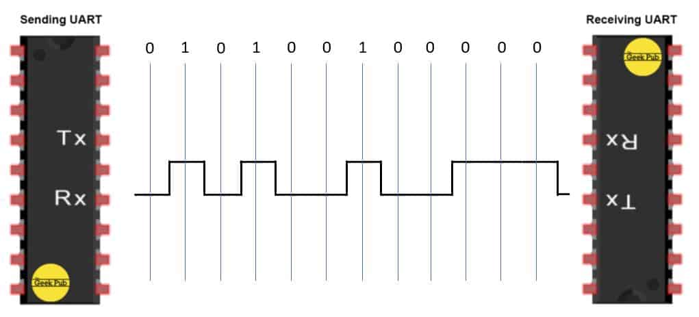 STEP 3: The receiving UART, now left with only the data frame places the bits back in parallel format and transmits them on the data bus.
 Final Thoughts on UARTs
As we wrap up our final thoughts on UART communication basics, its probably a good idea to cover the pros and cons of these devices. They’re great tools to have in our tool chest, but they’re not right for every situation.
The Advantages of UARTs
- Only two wires are required to transmit data
- There is no need to generate or maintain a serial clock line
- Pre-defined baud rate makes configuration and allows for simple designs; also a con
- UARTs support parity for error checking and error correction technologies
- Long history, very mature platform; the bugs have been long worked out
The Disadvantages of UARTs
- The big one: only two devices can communicate; no support for master/slave devices
- Pre-defined baud rate means devices can not negotiate faster or slower data rates; also a pro
- The data frame is relatively small compared to more modern techniques
- The speed of data transmission is relatively limited
RELATED: How I2C Serial Works

4.5