Blog
Using a 555 Timer in Astable Mode
In this tutorial we’re going to learn about using a 555 timer in astable mode. We’ve talked about the longevity of the venerable 555 timer and how its been around for almost 50 years at the time of this writing. It’s an incredibly versatile little integrated circuit with many fantastic uses. In this tutorial we’ll cover how to use the 555 timer to blink our blue LED. This will likely find its way into our R2-D2 build at some point in the future, so keep an eye out for that too!
Astable mode is by far the most common use a 555 timer and the one most people associate with it. The bistable and monostable modes should not be discounted, but the astable mode is where the magic is at.
What is a 555 Timer?
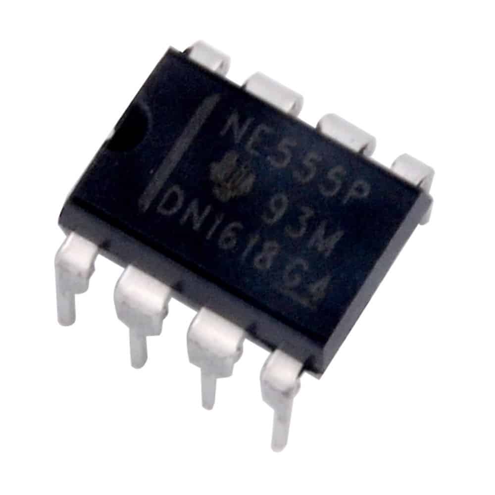
The 555 is called a timer, or “555 timer”. This is because it can pulse electrical currents for an exact amount of time based on the the values of resistors and capacitors connected to the timer. The timer has three modes of operation:
- Astable – This the most commonly used mode of the 555 timer. It cycles a repeating pulse of current for a specific amount of time. If you’ve ever seen a product that has some component that operates on a repeating cycle such as a flashing LED, there is a good chance that there is a 555 timer operating in astable mode behind the scenes. We’ll go over astable mode in our example below.
- Monostable – In this mode, the 555 timer outputs a pulse of current for a specific amount of time and then stops.
- Bistable – This mode of the 555 timer is different than the other two in that it does not use a capacitor or resistor to set a timing pulse, rather inputs from the trigger and reset pins control its states.
Watch the 555 Timer (Astable Mode) Video
Parts List for this Project
Here’s a quick parts list to get you going quickly on building this project:
| QTY | PART/LINK | ||
|---|---|---|---|
| 1X | [icon name=”microchip” prefix=”fas”] | 555 Timer IC | [icon name=”cart-plus” prefix=”fas”] |
| 1X | [icon name=”th” prefix=”fas”] | Solderless Breadboard | [icon name=”cart-plus” prefix=”fas”] |
| 1X | [icon name=”grip-lines” prefix=”fas”] | Jumper Wire Kit | [icon name=”cart-plus” prefix=”fas”] |
| 1X | [icon name=”ellipsis-h” prefix=”fas”] | Resistor Kit (10K Ohm) | [icon name=”cart-plus” prefix=”fas”] |
| 1X | [icon name=”lightbulb” prefix=”fas”] | LED Kit | [icon name=”cart-plus” prefix=”fas”] |
| 1X | [icon name=”circle” prefix=”fas”] | Capacitor Kit | [icon name=”cart-plus” prefix=”fas”] |
| 1x | [icon name=”battery-full” prefix=”fas”] | 9V Battery | [icon name=”cart-plus” prefix=”fas”] |
| 1x | [icon name=”pause-circle” prefix=”fas”] | 9V Battery Snap for Breadboard | [icon name=”cart-plus” prefix=”fas”] |
Some of these may be affiliate links. If you use them, it costs you nothing, but we may get a small commission that helps us keep making great content like this.
555 Timer in Astable Mode Example
Let’s go over Astable mode. In Astable the 555 timer uses a resistor and capacitor to create a cycling function. In this mode we can create a circuit with a repeatable action. Astable mode is the most common mode that you’ll find 555 timers used in. The values of the resistor and capacitor will determine the timing of this repeatable circuit. In our case we’re going to cause an LED to flash on a repeating interval using astable mode.
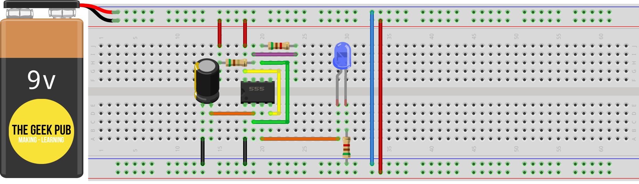
Wiring the 555 Timer for Astable Mode
To wire up the 555 timer for bistable operation, follow this wiring diagram.
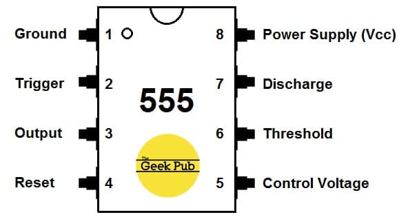
555 Timer Astable Pinout
- PIN 1 – Connected to ground (GND / Vcc-)
- PIN 2 – The trigger brings the the output HIGH when the voltage supplied to it drops below one-third of Vcc+
- PIN 3 – Outputs up to 200 mA of current at ~1.5 volts.
- PIN 4 – Connects to Vcc+. Bringing reset LOW will reset the 555.
- PIN 6 – The threshold brings the output LOW when its voltage is above two-thirds of Vcc+
- PIN 7 – When the output voltage is brought LOW, will discharge the capacitor to ground (GND)
- PIN 8 – Vcc+ Vonnected to the + side of the 9V battery (You can actually use any voltage between 4.5V and 15V to power the 555 in case you’re using a benchtop power supply).
Understanding Astable Mode on the 555 Timer
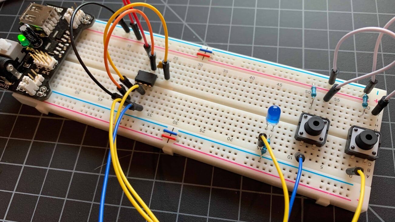
In astable mode, the output PIN cycles form HIGH to LOW continuously. As you can see in the wiring diagram, both the threshold pin and the trigger pin are connected to the 100uF capacitor. Therefore the the voltage levels will be identical on the trigger pin, threshold pin, and the 100uF capacitor.
When the circuit first receives power, the voltage is LOW at the capacitor, the threshold pin, and the trigger pin. Remember, if the trigger pin voltage is LOW, the output is HIGH. With the discharge pin its off state, current is able to flow through the 5.1K ohm resistors which in turn charges our 100uF electrolytic capacitor.
When the capacitor’s charge reaches two thirds of Vcc+, the output pin is deactivated. When the output pin is LOW, the discharge pin switches on causing the capacitor to drain to ground. Once the capacitor voltage drops to one-third of Vcc+, the trigger pin disables the discharge pin and the capacitor starts charging again.
The cycle repeats endlessly.
The 555 Timer Astable Mode in Action
Here’s a quick GIF of using a 555 timer in astable mode. It’s a great circuit that can be used in lots of projects.
The two 5.1K resistors and the 100uF capacitor can be changed to different values to speed up or slow down the rate at which the blue LED will blink. Additionally, you could use a potentiometer between pins 6 and 7 to make the circuit variable. Turning the knob on the potentiometer would control the blink rate of the blue LED.

RELATED: 555 Timer in Monostable Mode
We hope this tutorial has been easy to understand. If you have any questions or trouble making it work, give us a shout in the comments below and we’ll try to help!
5
0.5