Blog
Using a 555 Timer in Bistable Mode
In this tutorial we’re going to learn about using a 555 timer in bistable mode. As mentioned in our monostable 555 timer tutorial, these timers have been around almost 50 years, being released in 1971! And still today they make a perfect timer for hobbyist and DIY projects as they affordable and simple to understand.
What is a 555 Timer?
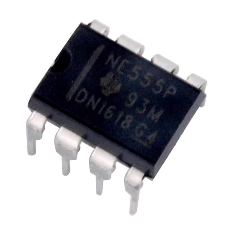 The 555 is called a timer, or “555 timer”. This is because it can pulse electrical currents for an exact amount of time based on the the values of resistors and capacitors connected to the timer. The timer has three modes of operation:
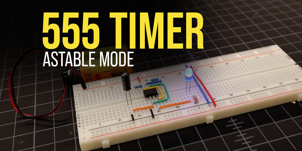
- Astable – This the most commonly used mode of the 555 timer. It cycles a repeating pulse of current for a specific amount of time. If you’ve ever seen a product that has some component that operates on a repeating cycle such as a flashing LED, there is a good chance that there is a 555 timer operating in astable mode behind the scenes.
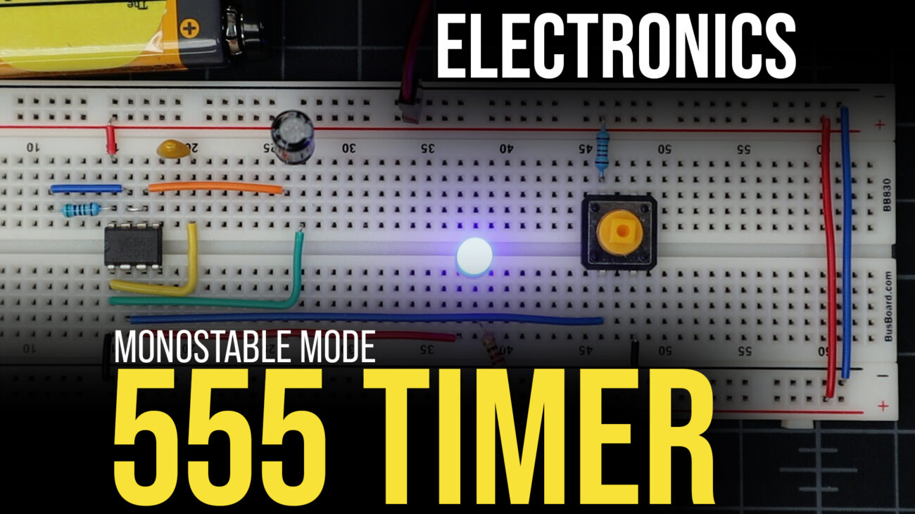
- Monostable – In this mode, the 555 timer outputs a pulse of current for a specific amount of time and then stops.
- Bistable – This mode of the 555 timer is different that the other two in that it does not use a capacitor or resistor to set a timing pulse, rather inputs from the trigger and reset pins control its states. We’ll go over bistable mode in our example below.
Parts List for this Project
Here’s a quick parts list to get you going quickly on building this project:
- 555 Timer IC
- Momentary Button (2)
- 10 pf Ceramic Capacitor
- Blue LED
- 10K Ohm (2) and 330 Ohm Resistors
- Project Breadboard and Breadboard Wires
- 9V Battery
- 9V Battery Snap (Breadboard Style)
555 Timer in Bistable Mode Example
In bistable mode, our 555 timer is going to work completely different from the other two modes. In this mode, we will have a trigger and a reset button that will control out timer. We’ve basically removed the timer components and turned the 555 into a relay of sorts. Pressing button one will activate the LED, while pressing button two will deactivate the LED.
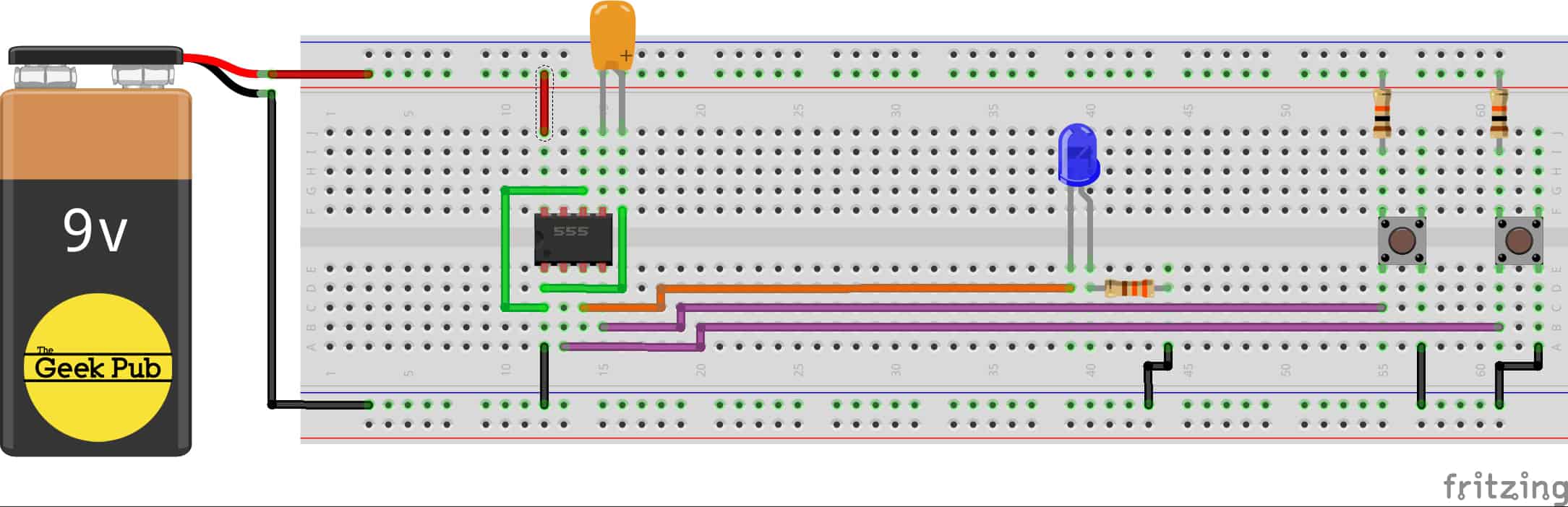
Wiring the 555 Timer for Bistable Mode
To wire up the 555 timer for bistable operation, follow this wiring diagram.
Understanding Bistable Mode on the 555 Timer
With bistable mode, pressing the button connected to the trigger allows current to flow from Vcc+ to ground (GND). This creates a state where the voltage at the trigger pin drops, this results in the the output PIN becoming switched which of course activates the blue LED. With the threshold pin being connected directly to ground (GND) it will never reach two-thirds voltage levels.
This means it will hold this state indefinitely and no change or “timing” will occur. We’ve sort of bypasses the 555’s logic so to speak. Pressing the reset button on the other hand will cause the voltage at the reset pin to become LOW. When this happens the output pin becomes switched off, and the LED is deactivated.
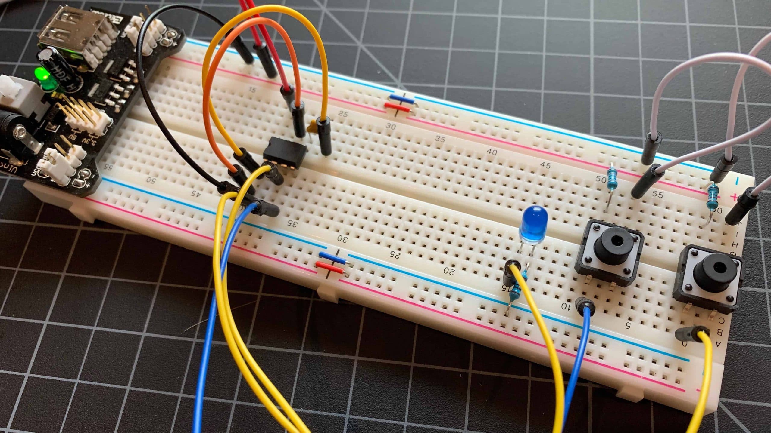
The 555 Timer Bistable Mode in Action
Here’s a quick GIF of using a 555 timer in bistable mode. It’s a very simple setup.
RELATED: 555 Timer in Monostable Mode
We hope this tutorial has been easy to understand. If you have any questions or trouble making it work, give us a shout in the comments below and we’ll try to help!
5