Blog
How I2C Works (I2C Explained Simply)
I2C is an extremely common protocol integrated into many products. It allows serial communications between many devices over just two wires. In this tutorial we will cover how I2C works and show some real world examples. If you plan on linking multiple Arduinos or connecting an Arduino to a
I2C Explained Simply
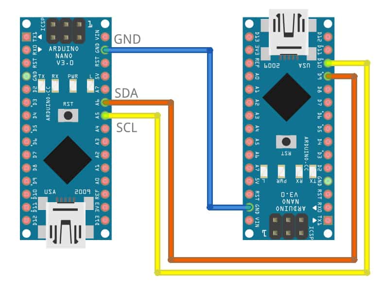
I2C allows you to connected numerous devices together using only two wires. This is great for connecting one or more Arduinos to a Raspberry Pi for example. We did just this in our R2-D2 project! But you can also use I2C to connect just two Arduinos together. Many devices also have I2C built in such as sensors, gyros, and display screens. You can have multiple or single masters controlling multiple or single slaves.
Most people say I2C only needs to wires to communicate, and while this is true, we highly recommend all I2C devices on your bus share a common ground wire. Many problems with garbled transmissions go away with just that one simple addition.
Let’s dive into the basics of I2C and talk about the wiring:
SDA is the Serial Data line. The master and slave devices send and receive data over this wire.
SCL is the Serial Clock line. It carries the clock signal generated by the master.
Like other similar protocols I2C is a serial communication protocol. I2C data is transferred bit by bit along a single SDA wire. It is also synchronous, which means the output of bits is synchronized using the SCL clock signal generated by the master. The clock signal is always controlled by the master, never the slave(s).
Here’s an excerpt from the I2C web page describing I2C:
| Wires Used | 2 |
| Speed | Standard Mode = 100Kbits Fast Mode = 400Kbits High Speed = 3.4Mbits Ultra Fast Mode = 5Mbits |
| Synchronous or Asynchronous | Synchronous |
| Serial Or Parallel | Serial |
| Maximum Number of Masters | Unlimited |
| Maximum Number of Slaves | 1008 |
How the I2C Protocol Works
I2C data is transferred in what we refer to as messages. Similar to other protocols (even networking protocols like Ethernet) messages are broken up into frames. Messages are uniquely addressed frames that identify the binary address of the slave the message is directed towards, followed by one or more data frames that contain the content being transmitted. Messages will also includes read/write bits, ACK/NACK bits, and start and stop conditions. Here’s what a message looks like, frame by frame:
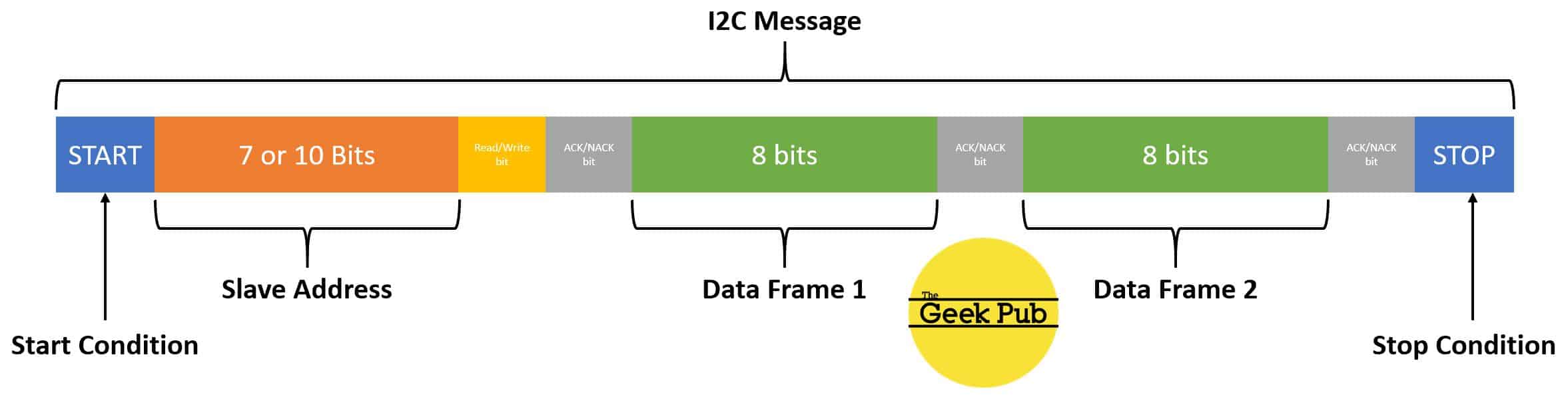
Start Condition is when the SDA line switches from a high to a low before the SCL line switches from high to low signaling the beginning of the communication.
The Address Frame is a 7 or 10 bit sequence that identifies a slave on the bus that the master wants to send the message to. This address uniquely identifies a a single slave on the bus. Slave addresses should never be duplicated on a single bus.
The Read/Write Bit is a single bit specifying whether the master is sending data to the slave by bringing the line low or requesting data from it by bringing the line high.
The ACK/NACK Bit follows each frame in a message. It is an acknowledge/no-acknowledge bit. If an address frame or data frame was successfully received, an ACK bit is returned to the sender from the receiving device.
Stop Condition is when the SDA line switches from a low to high after the SCL line switches from low to high signaling the end of the communication.
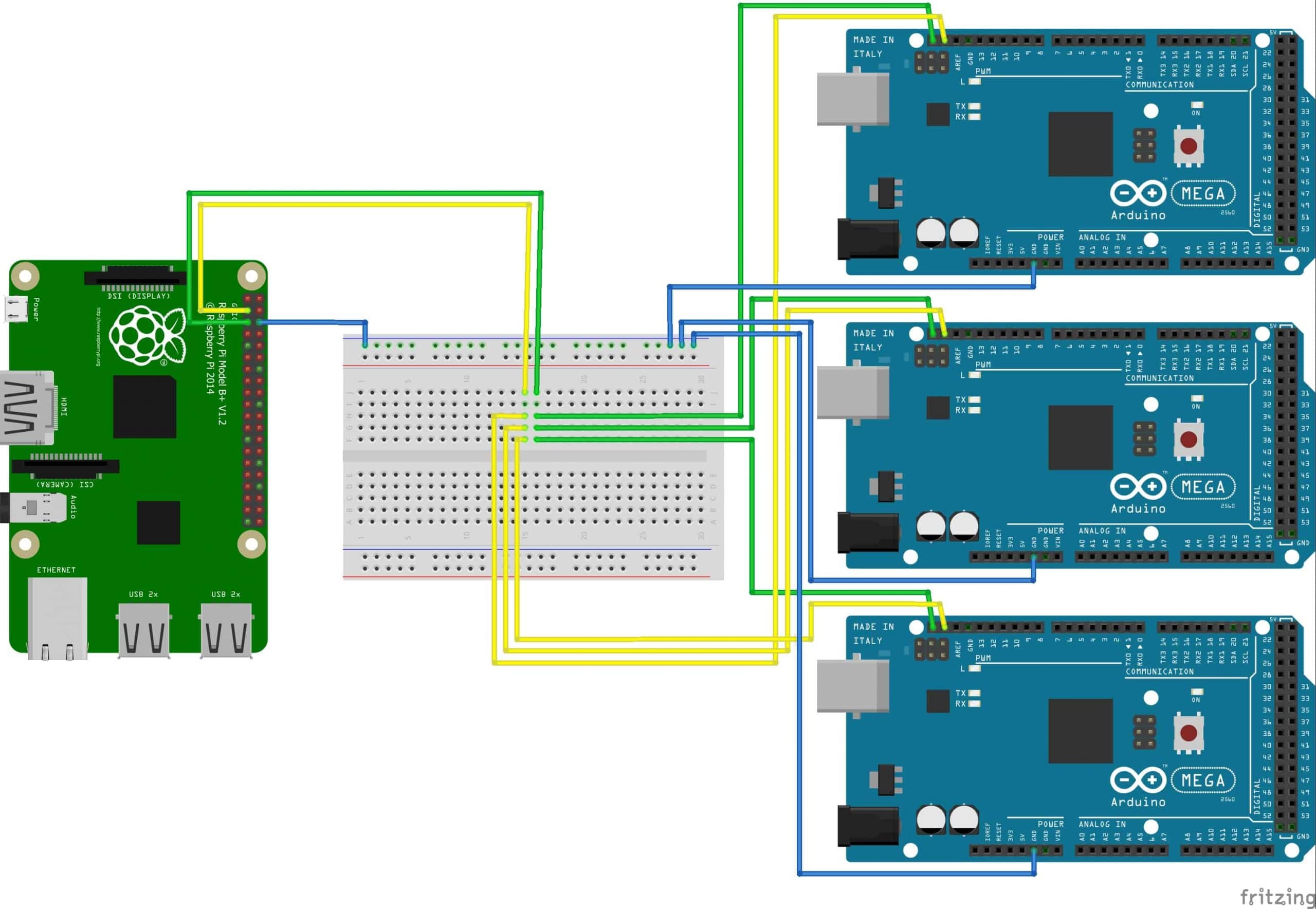
Wiring Multiple I2C Devices on a Single Bus
One question I often get is “If I2C is only two wire, how do you add multiple devices on the same bus?” Its actually not complicated at all. All of he devices on the bus are simply attached electrically to the same set of wires as shown below. This could be physical wire or traces on a circuit board.
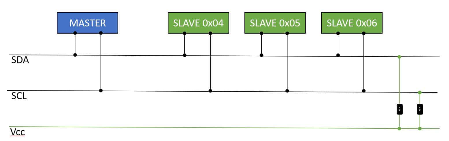
If you’re prototyping the simplest way is to use a breadboard between your devices. See this example below of a single
How I2C Messaging Works
As we learn how I2C works, let’s break down the message piece by piece and understand how each component works.
How Addressing Works
Like most protocols where numerous devices have the potential to exist on a bus, I2C needs a way to signal a specific device to listen to the message, and for other devices to ignore the message. I2C does this with an address frame. The address frame always follows immediately behind the start condition.
Every device on the bus will listen to the start condition, followed by the address. If the address matches a specific slaves address on the bus, that slave will send the ACK bit by bring the SCL line low. This is how a slave on the I2C bus acknowledges the master.
7 or 10 bit Addresses
It is important to understand that I2C slave addresses can be either 7 or 10 bit. To do this, there are actually two addresses sent across the bus and therefore two address frames. The first address is a special 7 bit address of 0x92. No 7 bit devices should ever be set to 0x92 and therefore all 7 bit addressed devices should ignore this address and the rest of the message. Immediately following this special address follows another address frame for the 10 bit devices. This is how 10 bit addressed devices can exist on the same bus with 7 bit devices and everything remains compatible.
How the Read/Write Bit Works
I2C has two special ways of working with slaves. The Master can send data to the slave, or it can request data from the slave. After the address bit follows what is called an I2C read/write bit. If the master wishes to receive data from the slave it sends a read bit by bringing the line high. If the master wishes to send data to the slave it sends a write bit by bringing the line low.
How the Data Frame Works
Immediately following the read/write bit is an ACK/NACK bit. Only after the master receives this bit, can data frame transmissions begin.
The 8 bit data frame is always transmitted with the most significant bit first. The most significant bit (also called the high-order bit) is the bit position in a binary number having the greatest value. Reversing this order would cause transmission to fail. After each frame is sent it is acknowledged by either the master or the slave device depending on the whether data is being transmitted to a slave or being received from a slave (based on the previous read/write bit selection).
Finally, when all frames have been sent the master will set the stop condition. This terminates the send/receive process. The end stat is the SDA line will be brought high, after the SDA line is brought high. The SDA line will remain high.
How I2C Works with Multiple Masters
Because I2C is an address based protocol, each slave has a 7 or 10 bit address. This allows the master to communicate with up to 128 slaves on a 7 bit bus or up 1023 slaves on a 10 bit bus.
Note: In most configurations of I2C where multiple devices will share a bus, you will need 4.7k ohm pull up resistors from VCC attached to the SDA and SCL lines. However, some devices like the
Here’s where things start to get interesting. I2C can also support multiple masters! That’s right, you can have multiple masters on the bus with a single or multiple slave devices. If you’re like me your first questions might be “What stops data collisions?” or “Who controls the clock line?”
To stop collisions (two masters transmitting at the same time), each master is responsible for first checking the state off the SDA line to see if it is low or high before transmitting. When the SDA line is in its low state, it means another master is actively using the line and it must wait.
To handle the clock problem only one master at a time can run the clock. At the beginning of communications the new master takes over control of the SCL line and releases it at the end of its transmission.


4.5
3.5
4
0.5