Blog
Controlling an Arduino from a Web Page
When I got my first Arduino the first thing I thought was “Wow! I’d love to be able to control this thing from a web page!”, but of our course I didn’t have an Ethernet shield. So recently I decided to grab a shield from Amazon and see what I could do. First things first I needed to create a simple sketch to draw a web page and accept input. So in this tutorial that’s exactly what we will cover!
How to Control an Arduino from a Web Page
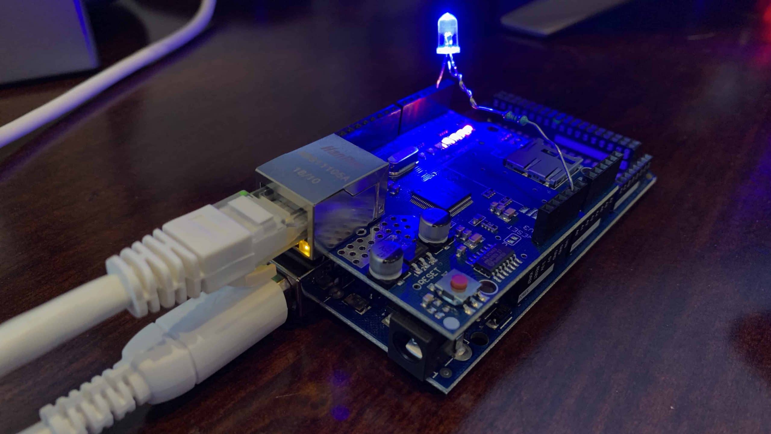
In this project tutorial we’re going to setup an Arduino with an Ethernet shield that will allow us to control a blue LED from a web browser (of course you can use another color if you desire!).
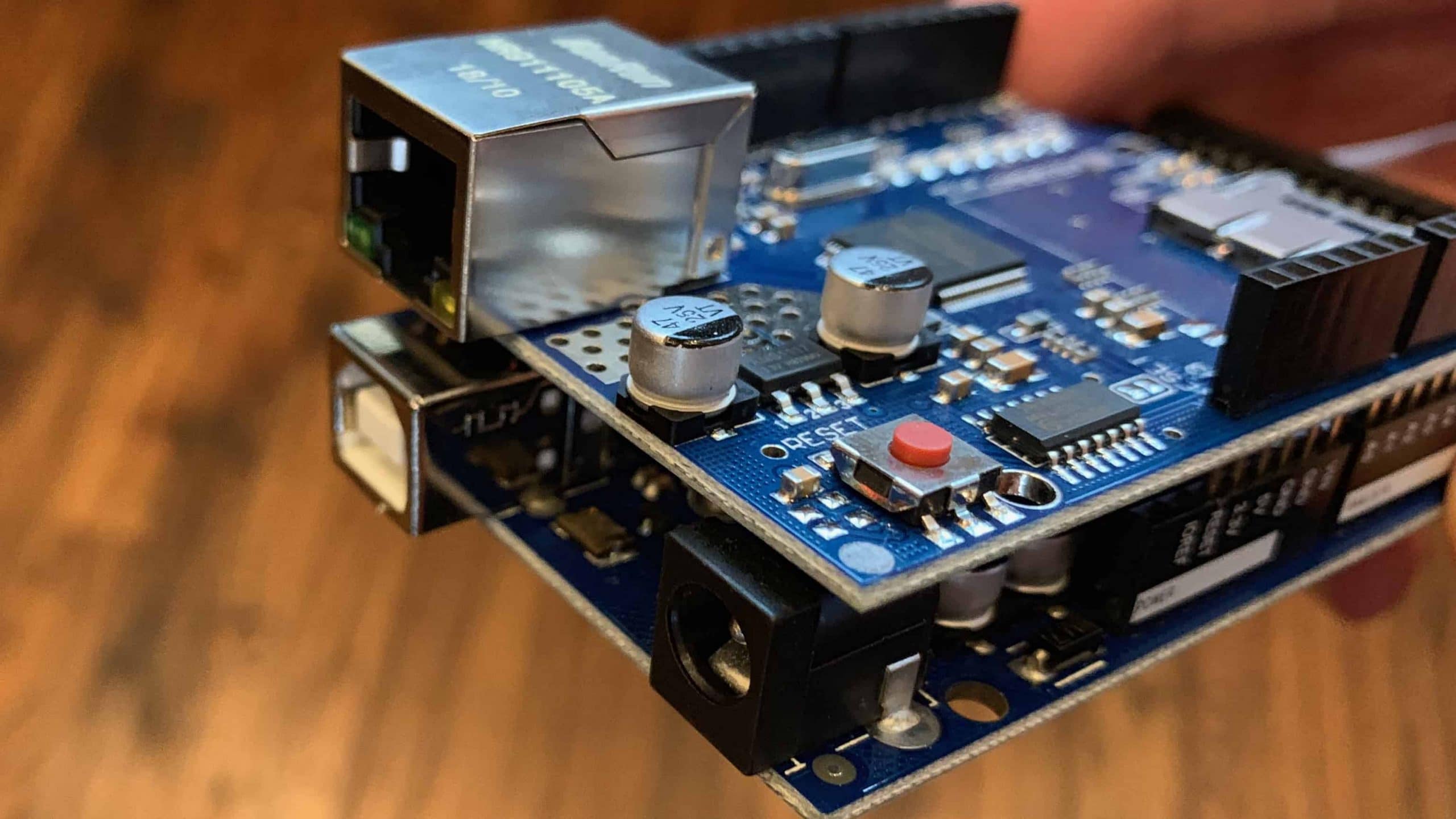
The first thing you need to do, before we even think about controlling an Arduino from a web page is to connect the Ethernet shield to the Arduino. It simple aligns with the pins and presses down. Don’t press it down too far however, or the bottom of the Ethernet shield may make contact with the top of the USB port. This could cause your shield to short out. The shield used in this project is the Wiznet W5100 variant made by Sunfounder (a clone of the official Arduino W5100).
Parts List for this Project
If you don’t already have the components for this list, here’s our simple parts list:
Wiring Diagram for Ethernet Controlled LED
Normally for a project like this I would just use the onboard LED assigned to pin 13. Unfortunately there are to major issues with that approach with this project. First, the LED is covered and very hard to see thanks to the Ethernet Shield. The second and more serious reason is that pin 13 is used by the W5100 Ethernet shield. So for this project we’re just going to plug a blue LED attached to a 10K ohm resistor attached to pin 2.
The wiring should follow this diagram:
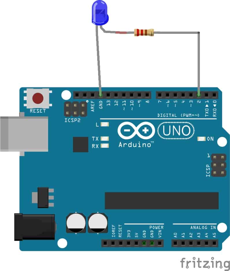
And that’s literally all there is to wiring. Attach the board to Ethernet and plug it into your PC via USB. Add the following code and upload it to the Arduino. You’re ready to start controlling an Arduino from a web page!
You’ll likely want to change the IP address I’ve chosen (192.168.1.212) to one that suits the subnet of your home network, but other than that nothing else needs to be adjusted.
[code language=”cpp”]
// The Geek Pub – Controlling an Arduino Pin from a WebPage
// Freely distributable with attribution and link to TheGeekPub.com
#include "SPI.h"
#include "Ethernet.h"
byte mac[] = { 0xDE, 0xAD, 0xBE, 0xAD, 0xEE, 0xBE }; //physical mac address
byte ip[] = { 192, 168, 1, 212 }; // IP address in LAN – need to change according to your Network address
byte gateway[] = { 192, 168, 1, 1 }; // internet access via router
byte subnet[] = { 255, 255, 255, 0 }; //subnet mask
EthernetServer server(80); //server port
String controlString; // Captures out URI querystring;;
int blueLEDPin = 2; // pin where our blue LED is connected
void setup(){
pinMode(blueLEDPin, OUTPUT); // change pin 2 to OUTPUT pin
// Initialize the Ethernet
Ethernet.begin(mac, ip, gateway, subnet);
server.begin();
}
void loop(){
// Create a client connection
EthernetClient client = server.available();
if (client) {
while (client.connected()) {
if (client.available()) {
char c = client.read();
//read the HTTP request
if (controlString.length() < 100) {
// write characters to string
controlString += c;
}
//if HTTP request has ended– 0x0D is Carriage Return \n ASCII
if (c == 0x0D) {
client.println("HTTP/1.1 200 OK"); //send new page
client.println("Content-Type: text/html");
client.println();
client.println("<html>");
client.println("<head>");
client.println("<title>The Geek Pub Arduino Ethernet Test Page</title>");
client.println("</head>");
client.println("<body>");
client.println("<img src=\"https://cdn.thegeekpub.com/wp-content/uploads/2018/01/the-geek-pub-big-logo-new.jpg\") style=\"width: 55%; margin-left: auto; margin-right: auto; display: block;\" />");
client.println("
<h1 style=\"color: blue; font-family: arial; text-align: center;\">THE GEEK PUB ARDUINO ETHERNET TEST PAGE</h1>
");
client.println("
<h2 style=\"color: green; font-family: arial; text-align: center;\">LED ON/OFF FROM WEBPAGE</h2>
");
client.println("
<hr>
");
client.println("
<h2 style=\"color: blue; font-family: arial; text-align: center;\"><a href=\"/?GPLED2ON\"\">Turn On The Blue LED</a> – <a href=\"/?GPLED2OFF\"\">Turn Off the Blue LED</a>
</h2>
");
client.println("</body>");
client.println("</html>");
delay(10);
//stopping client
client.stop();
// control arduino pin
if(controlString.indexOf("?GPLED2ON") > -1) //checks for LEDON
{
digitalWrite(blueLEDPin, HIGH); // set pin high
}
else{
if(controlString.indexOf("?GPLED2OFF") > -1) //checks for LEDOFF
{
digitalWrite(blueLEDPin, LOW); // set pin low
}
}
//clearing string for next read
controlString="";
}
}
}
}
}
[/code]
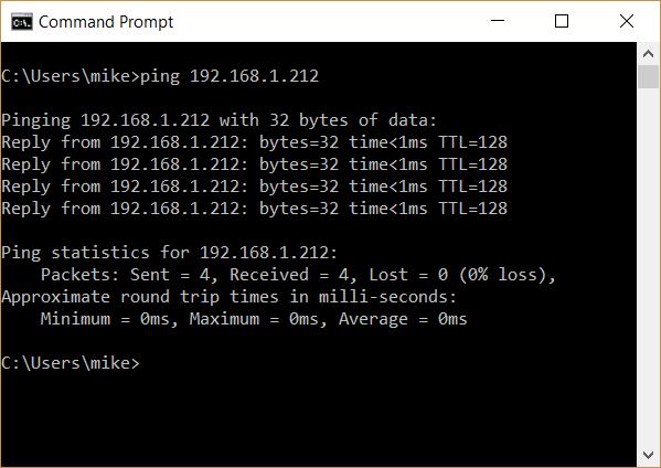
Open a command prompt and type ping 192.168.1.212 (or your IP) and you should see the following, verifying that your Arduino is in fact properly connected to the network:
Open a browser and type in http://192.168.1.212 (or the address you picked on your network) and you should see the following screen:
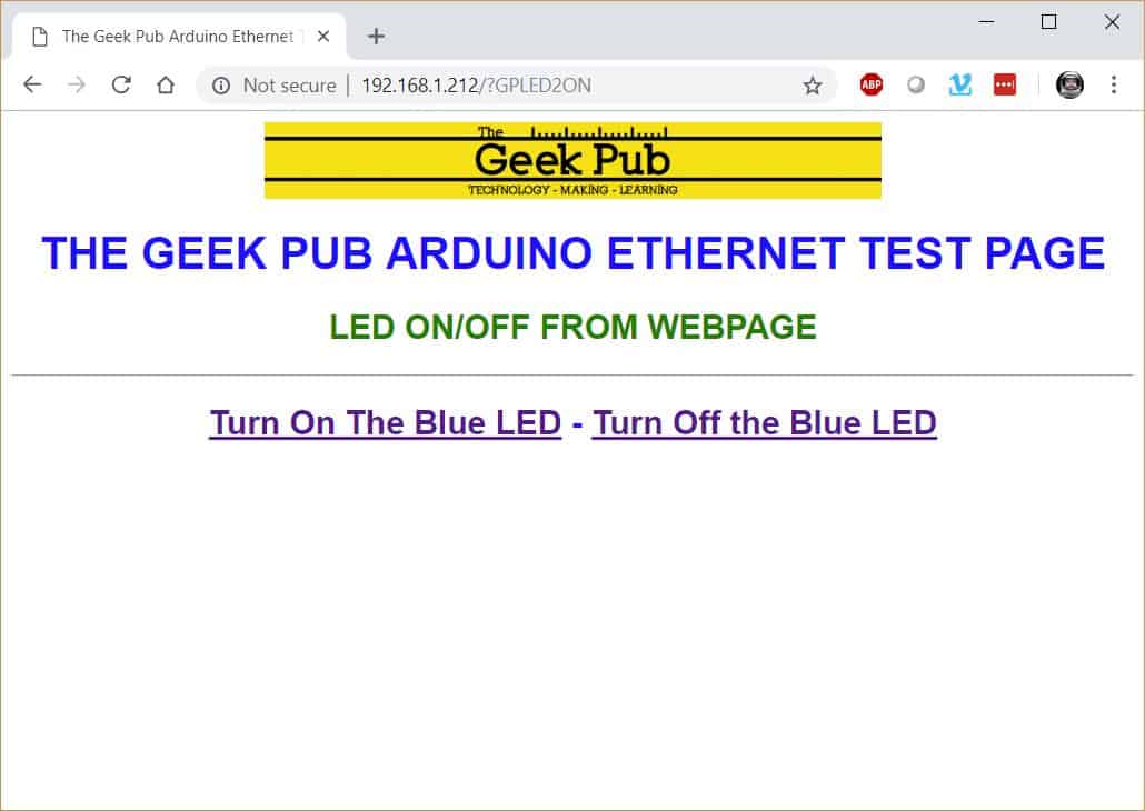
Clicking the “Turn on The Blue LED” should light the LED while clicking “Turn Off the Blue LED” should turn it off.
Understanding the Ethernet Shield Web Page Sketch
The W5100 Ethernet Shield for the Arduino interfaces with the Arduino over the SPI connector (this is the small 4 pin block in the middle of the Arduino. Therefore, using the Ethernet Shield will require both the SPI library and the Ethernet library to be included in your project.
[code language=”cpp”]
#include "SPI.h"
#include "Ethernet.h"
[/code]
The next section of code assigns the MAC address and IP address to the Ethernet shield and assigns the server to port 80, which is the standard web server location.
[code language=”cpp”]
byte mac[] = { 0xDE, 0xAD, 0xBE, 0xAD, 0xEE, 0xBE };
byte ip[] = { 192, 168, 1, 212 };
byte gateway[] = { 192, 168, 1, 1 };
byte subnet[] = { 255, 255, 255, 0 };
EthernetServer server(80);
[/code]
Next, we need a variable to use for our blue LED pin, along with a “control” variable to capture the URI query string data. We will send ?GPLED2ON to the webpage to turn the LED and ?GPLED2OFF to turn it off. controlString will capture these commands.
[code language=”cpp”]
String controlString;
int blueLEDPin = 2;
[/code]
The setup section of our code sets pin 2 to OUTPUT in order to power our LED when we set pin 2 high. Ethernet.begin starts the Ethernet shield and assigns it the addresses we specified earlier. Server.begin starts the web server listening on port 80.
[code language=”cpp”]
pinMode(blueLEDPin, OUTPUT);
Ethernet.begin(mac, ip, gateway, subnet);
server.begin();
[/code]
For the final section, I am not going to go into much detail as it builds an HTML page that will be delivered to your browser. The fundamentals of HTML are beyond the scope of this tutorial.
The fundamentals are that the loop routine is listening for a command and when it receives it, it will use the digitalWrite function to change the state of the blue LED.
Other Ideas for Controlling an Arduino from a Web Page
Beyond controlling a simple LED there are so many other uses for this technology. You could use a relay to control something with much higher voltage or current draw that the Arduino can handle. For example a pump in a well house. You could connect lighting for home automation, or control dust collection systems in your wood shop. The ideas for this are almost endless.
Wi-Fi Shield
While we covered the Ethernet shield in this article, is important to note that Wi-Fi shields are available for controlling an Arduino from a web page wirelessly! This is perfect for battery operated projects like robots and vehicles.
Be sure to leave a comment below with the results of your project!


3.5