Sensor Wiki: KY-039 Heartbeat Sensor
This wiki article covers the KY-039 heartbeat sensor (sometimes called the KY-03 pulse sensor). Included are wiring diagrams, code examples, pinouts, and technical data. This sensor is designed for use in reliably detecting heartbeat or pulse rate using an Arduino or Raspberry Pi.
Content
- Sensor/Module Image Gallery
- Description and Technical Data
- Device Pinout
- Projects that use this Sensor/Module
- Code Examples
- Code example for Arduino
- Code example for Raspberry Pi

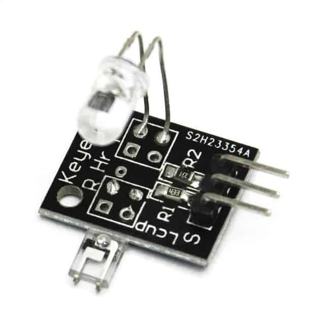
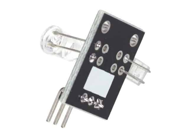
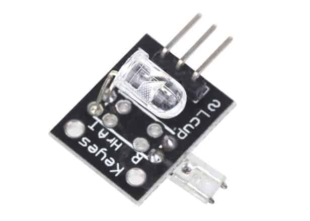
Sensor Module Image Gallery

Description and Technical Data
The KY-039 heartbeat sensor is designed to detect a pulse while a human finger is place between the infrared diode and the photo transistor. The pulse will be represented on the signal output pin.
This sensor works by using a photo transistor to detect the presence of light, in this case how much light is passing through a finger. When blood moves, the amount of light changes and that change can be detected as a pulse.
Tech Specs for the KY-039 Heartbeat Sensor:
- Coming soon.
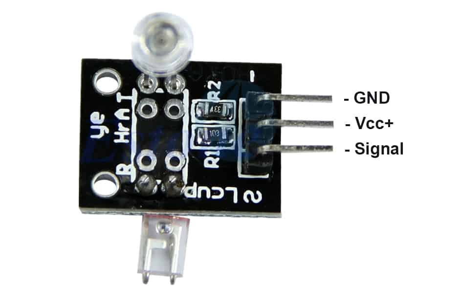
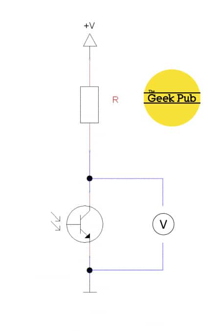
Device Pinout & Schematics
This module has three pins: GND, Vcc+, and Signal. The pinout is as follows:
The KY-039 heartbeat sensor schematic is as follows:
Our Projects that Use this Sensor
We do not currently have any Geek Pub projects that use the heartbeat sensor. We will be creating one soon though so check back!
Code Examples
You’ll find below code examples of using the KY-039 heartbeat sensor with both Arduino and Raspberry Pi (Python).
KY-039 Heartbeat Sensor Code Example for Arduino
The following code example is for the Arduino. This code will read the Analog Output Sensor value and write it to the serial console, pause 500ms and repeat.
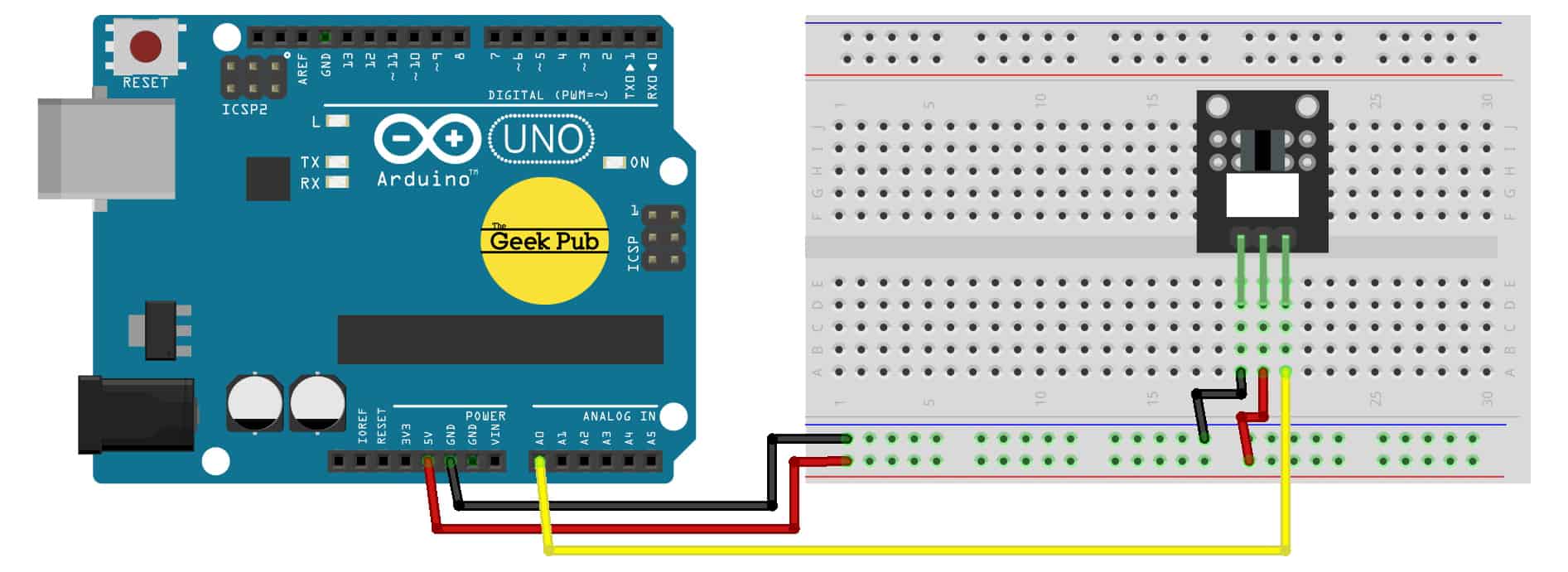
Arduino Wiring:
- KY-039 Sensor GND to Arduino GND
- KY-039 Sensor Signal to Arduino PIN A0
- KY-039 Sensor Vcc+ to Arduino +5V
int ledPin=13;
int analogPin=0;

void setup()
{
// The included LED of the Arduino (Digital 13), will be used as output here.
pinMode(ledPin,OUTPUT);

// Serial output initialization
Serial.begin(9600);
Serial.println("Heartbeat detection example code");
}

const int delayMsec = 60; // 100msec per sample

// The main program has two tasks:
// – The LED will light up after detecting a heart beat
// – Calculating of the pulse and outputting of it at the serial out.

void loop()
{
static int beatMsec = 0;
int heartRateBPM = 0;
Serial.println(rawValue);
if (heartbeatDetected(analogPin, delayMsec)) {
heartRateBPM = 60000 / beatMsec;
// LED-output for the heart beat heart beat
digitalWrite(ledPin,1);

// Output of the serial data
Serial.print(rawValue);
Serial.print(", ");
Serial.println(heartRateBPM);

beatMsec = 0;
} else {
digitalWrite(ledPin,0);
}
delay(delayMsec);
beatMsec += delayMsec;
}
KY-039 Hearbeat Sensor Code Example for Raspberry Pi
The following code example is for the Raspberry Pi using the Python programming language. This code will read the Analog Output Sensor value and write it to the terminal window, pause 500ms and repeat.
Raspberry Pi Wiring:
- Coming Soon!
We hope this wiki article has been helpful to you. Please leave a comment below if you have any questions or comments, as we try to keep these articles constantly up to date.
Are you going to apply in Rasberry Pi diagram in Python?
when would the raspberry pi code be up we need it immediately we are dying from our group project
Same here