Sensor Wiki: KY-019 Relay Module
This wiki article covers the KY-019 relay module. Included are wiring diagrams, code examples, pinouts, and technical data. This module is designed to allow the Arduino or Raspberry Pi to control high voltage device through a magnetic relay using low voltage GPIO pins.
Content
- Sensor/Module Image Gallery
- Description and Technical Data
- Device Pinout
- Projects that use this Sensor/Module
- Code Examples
- Code example for Arduino
- Code example for Raspberry Pi

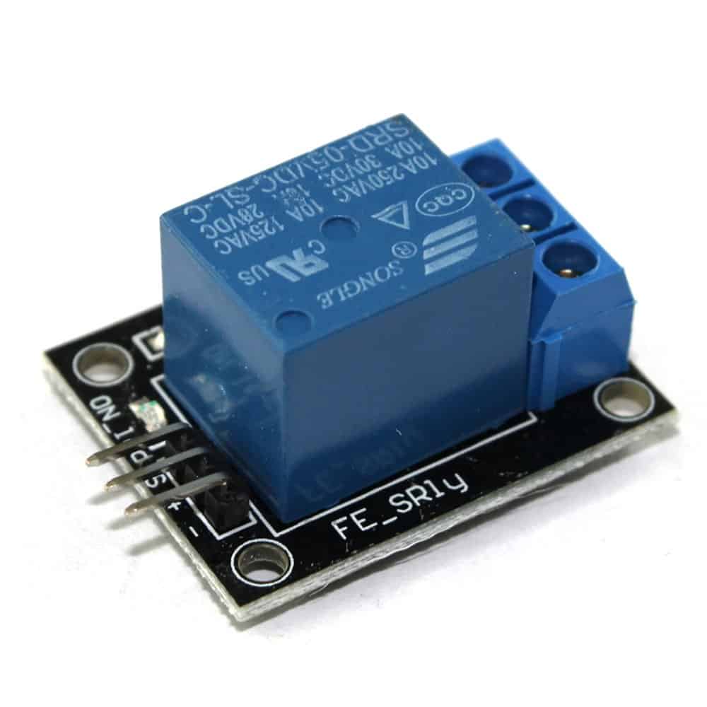
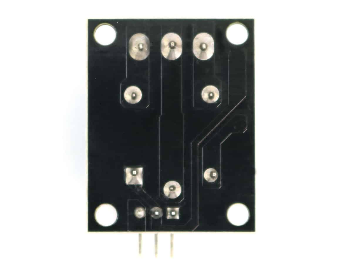
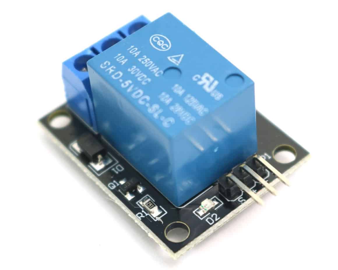
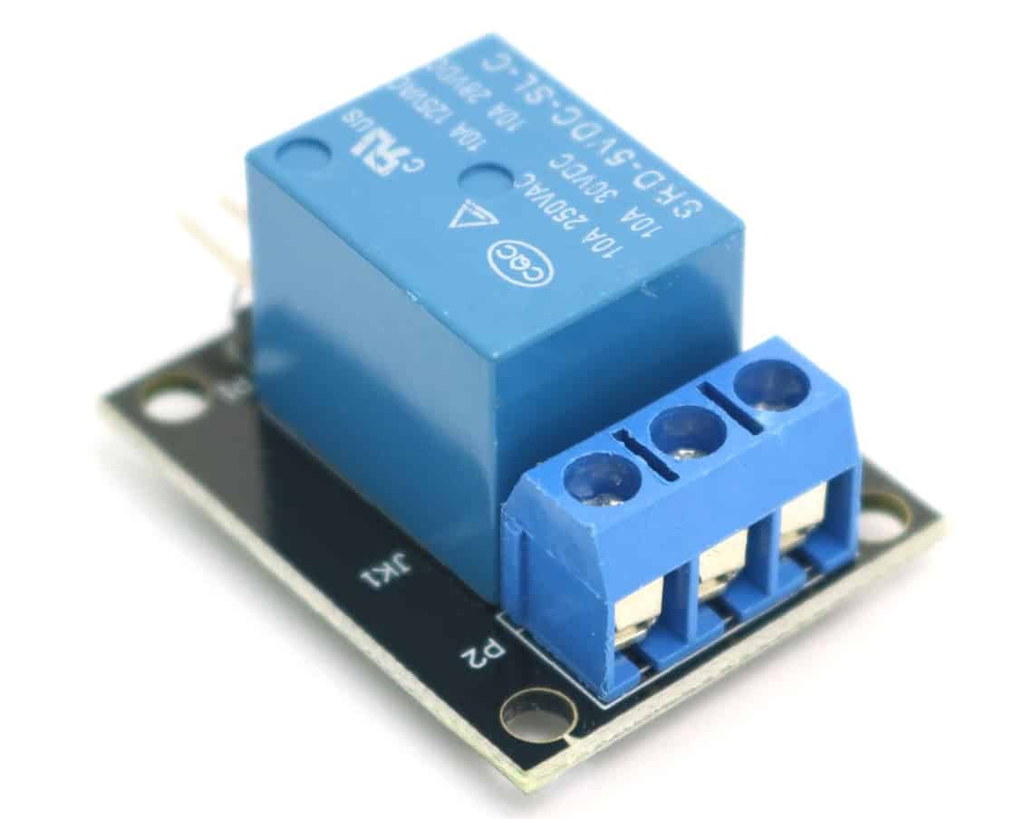
Sensor Module Image Gallery
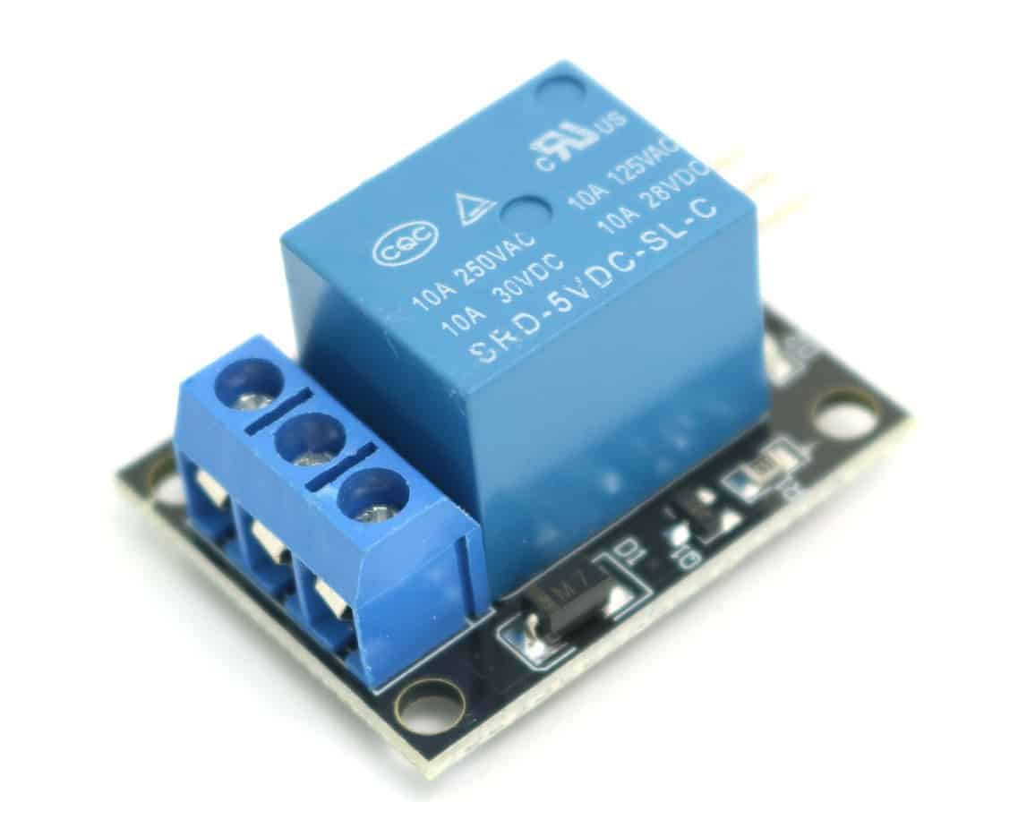
Description and Technical Data
The KY-019 relay module has two contacts, normally open (NO) and normally closed (NC) that are operated by pulling the signal pin HIGH. This allows low voltages devices such as the Arduino or Raspberry Pi to safely control high voltage devices. The high voltage side of the relay can operate up to 250V AC or up to 30V DC.
WARNING: If you’re not familiar with the precautions that should be taking when working with voltages over 24V please seek additional guidance before connecting this relay module to high voltage sources such as household mains lines of 120-240V AC. These voltage levels can be very dangerous.
Tech Specs for the KY-019 Relay Module:
- Board Components:
- 1MOhm Resistor,
- SMD LED,
- 1N4007 diode
- 5V DC relay
- Min/Max Input Voltage: +3.3V to +12V DC
- Max Contact Voltage:
- 30V 10A DC
- 250V 10A AC
- Dimensions: 1.06in X 1.34in (27mm X 34mm)
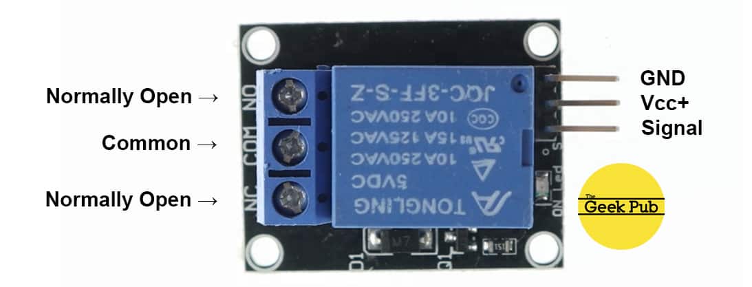
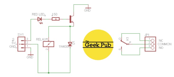
Device Pinout & Schematics
This module has six pins, Normally Open, Normally Closed, Common, GND, Vcc+, and Signal.
The normally open and normally closed contacts operate opposite of each other. Normally closed will pass current until the signal line is activated. Normally Open will not pass current until the signal line is activated. The common terminal is shared between the two contacts. You can use either the NC or NO terminals, or both at the same time.
The KY-019 pinout is as follows:
The KY-019 relay module schematic is as follows:
Our Projects that Use this Sensor
The following Geek Pub projects use the 5v KY-019 relay module:
Code Examples
You’ll find below code examples of using the KY-019 relay module with both the Arduino and the Raspberry Pi (Python).
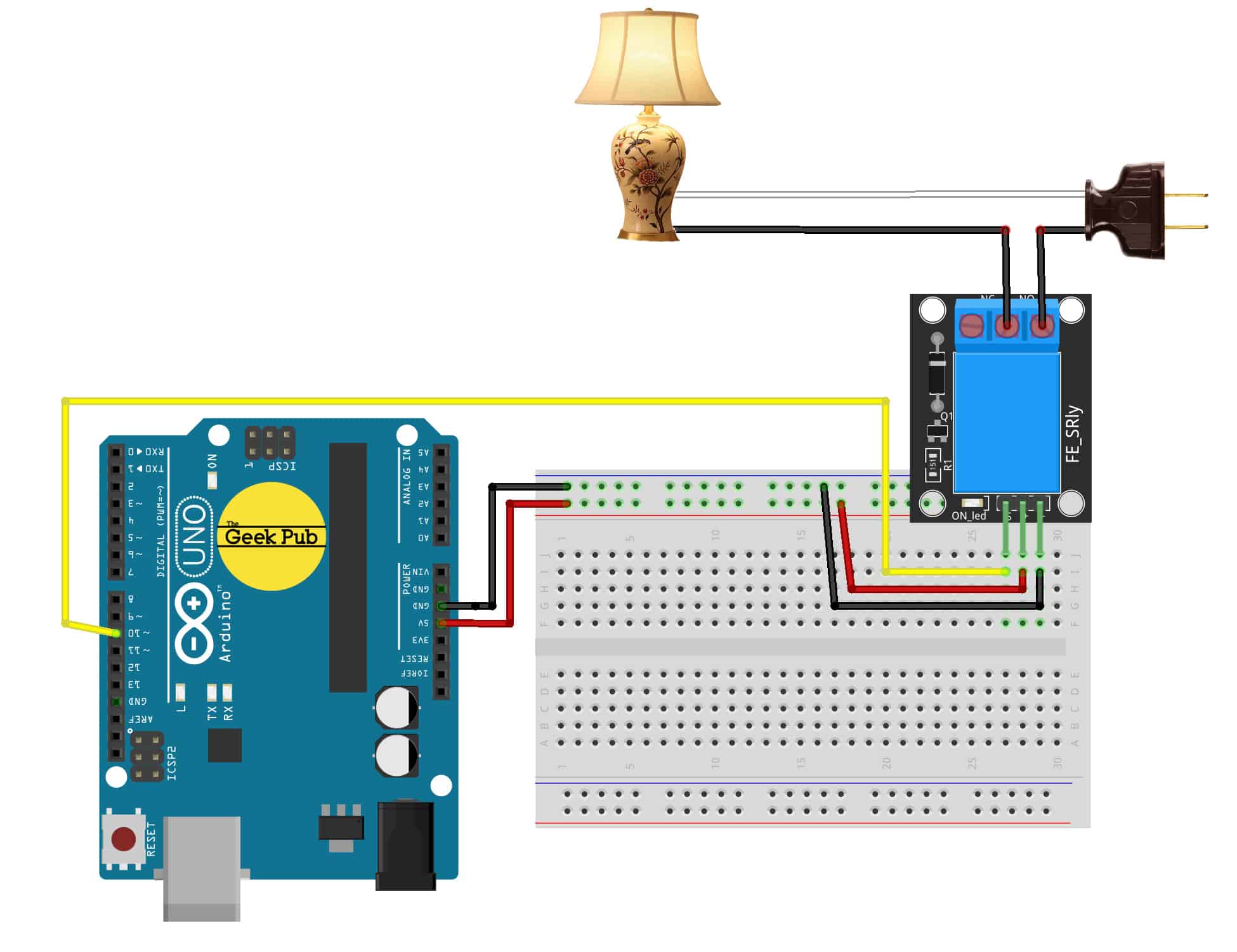
KY-019 Relay Module Code Example for Arduino
The following code example is for the Arduino. This code will activate the relay for 2 seconds, and then deactivate it for two seconds. During the activation devices attached to the normally open contact will turn on (current will flow) and devices connected to the normally closed pin will turn off (no current will flow).
Arduino Wiring:
- KY-019 Module GND to Arduino GND
- KY-019 Module Vcc+ to Arduino +5V
- KY-019 Module Signal to Arduino PIN 10
int GPRelayPIN = 10; // define the relay signal pin

void setup ()
{
  pinMode (GPRelayPIN, OUTPUT); // set the pin to output
}

void loop ()
{
  // activate the relay
  // normally closed pin stops sending current
  // normally open pin starts sending current
  digitalWrite (GPRelayPIN, HIGH);
  delay (2000); // pause for 2 seconds

  // deactivate the relay
  // normally open pin stops sending current
  // normally closed pin starts sending current
  digitalWrite (GPRelayPIN, LOW);
  delay (2000); // pause for 2 seconds
}
KY-019 Relay Module Code Example for Raspberry Pi
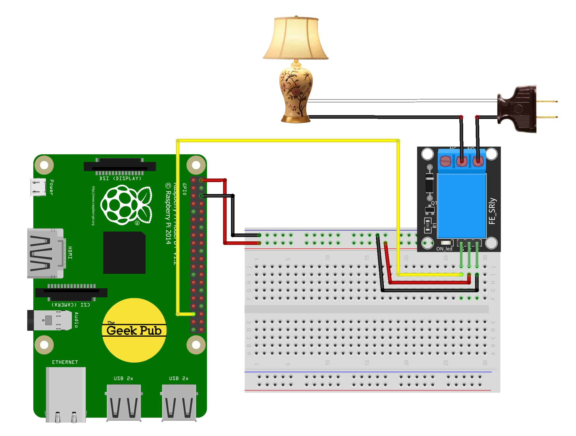
The following code example is for the Raspberry Pi using the Python programming language. This code will activate the relay for 2 seconds, deactivate the relay for 2 seconds, and then loop. Try connecting your lamp to the normally open or normally closed contacts to see how they operate differently when you disconnect power from the relay.
Raspberry Pi Wiring:
- KY-019 Module GND to Raspbery Pi GND
- KY-019 Module Vcc+to Raspberry Pi PIN 2
- KY-019 Module Signal to Raspberry Pi PIN 18
import RPi.GPIO as GPIO     # import GPIO librarie

GPIO.setmode(GPIO.BCM)

GPRelayPIN = 21
GPIO.setup(GPRelayPIN, GPIO.OUT)
GPIO.output(GPRelayPIN, False)

while True:
    # activate the relay
    # normally closed pin stops sending current
    # normally open pin starts sending current
    GPIO.output(GPRelayPIN, True)
    time.sleep(2) #sleep 2 seconds

    # deactive the relay
    # normally closed pin starts sending current
    # normally open pin stops sending current
    GPIO.output(GPRelayPIN, False) # NC is now connected through
    time.sleep(2)
We hope this wiki article has been helpful to you. Please leave a comment below if you have any questions or comments, as we try to keep these articles constantly up to date.
The schematics ist wrong! Using a NPN transistor the emiter must be connected to GND. So exchange emiter and collector and it (may be) correct