Sensor Wiki: KY-012 Active Piezo-Buzzer Module
This wiki article covers the KY-012 active piezo-buzzer module. Included are wiring diagrams, code examples, pinouts, and technical data. This sensor is a fantastic sensor for providing simple audible feedback to your projects and can be setup with the absolute minimum of effort.
Content
- Sensor/Module Image Gallery
- Description and Technical Data
- Device Pinout
- Projects that use this Sensor/Module
- Code Examples
- Code example for Arduino
- Code example for Raspberry Pi

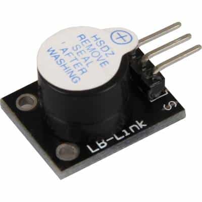
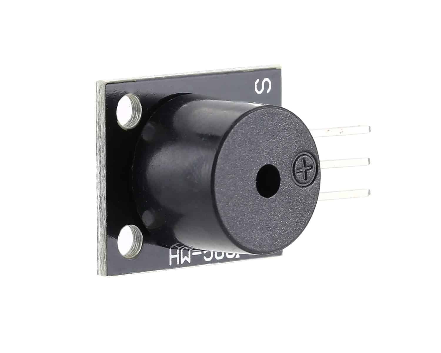
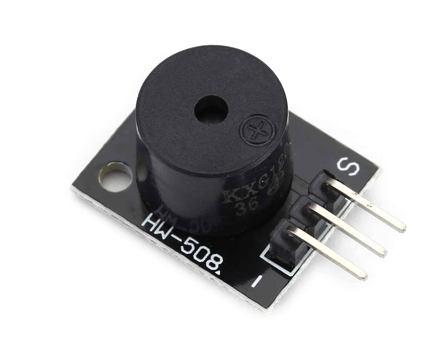
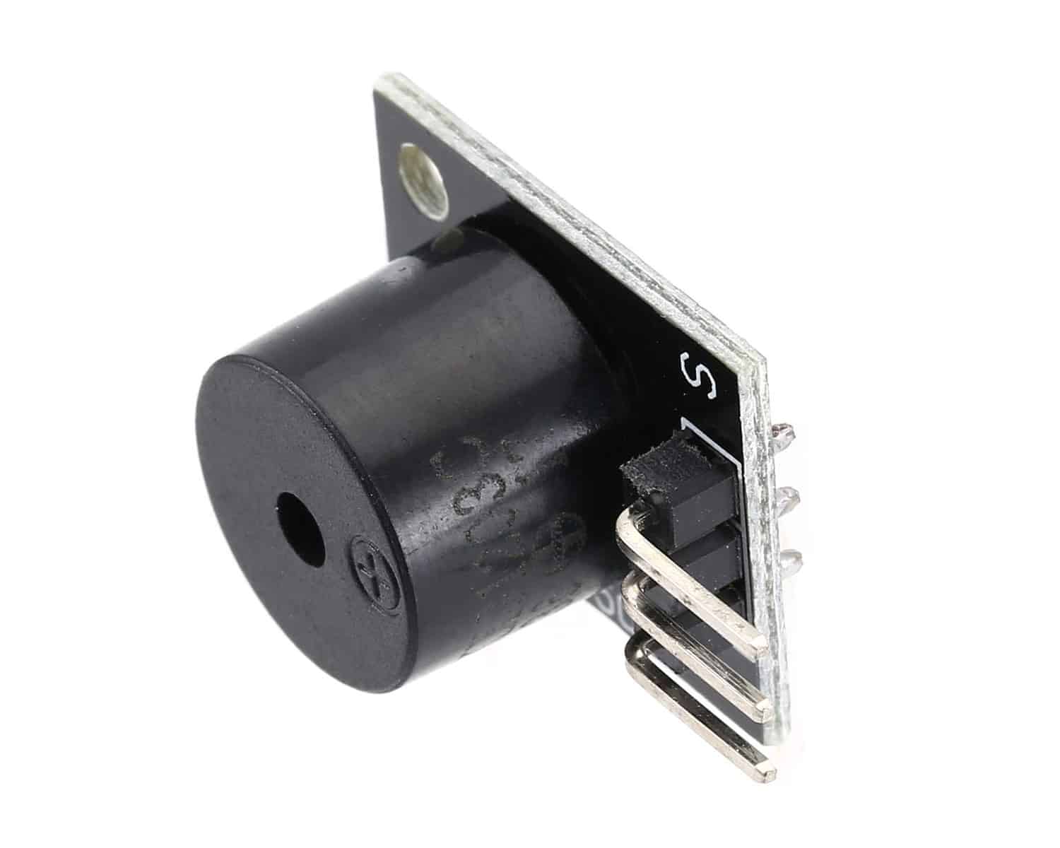
Sensor Module Image Gallery
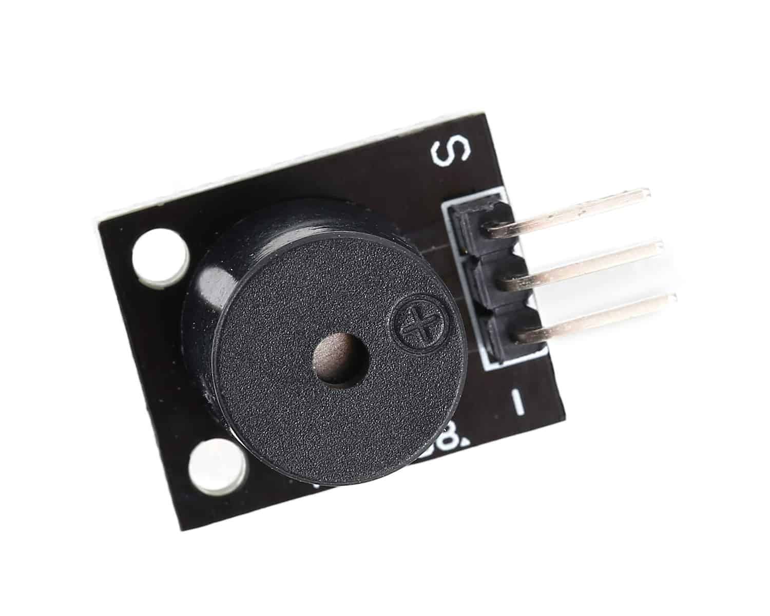
Description and Technical Data
The KY-012 active piezo buzzer is a 3-pin module that creates an audible sound at 2.5 kHz without the need for pulse width modulation (PWM) or any additional complex code. The only requirement is to set the signal pin to HIGH.
Tech Specs for the KY-012 Active Buzzer:
- Min/Max Operating Voltage +3.3V to +5V
- Maximum Current: 30mA
- Resonance Frequency: 2500Hz ± 300Hz continous
- Minimum Sound Output 85Db @ 4in (10cm)
- Storage Temperature: -22°F to 221°F (-30°C to 105°C)
- Operating Temperature: -4°F to 158°F (-20°C to 70°C)
- Dimensions: 0.73in X 0.59in (18.5mm X 15mm)
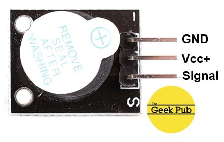
Device Pinout & Schematics
This module has three pins: GND, Vcc+, and Signal.
Our Projects that Use this Sensor
The following Geek Pub projects use the KY-012 active piezo-buzzer.
Code Examples
You’ll find below code examples of using the KY-012 active piezo buzzer with both Arduino and Raspberry Pi (Python).
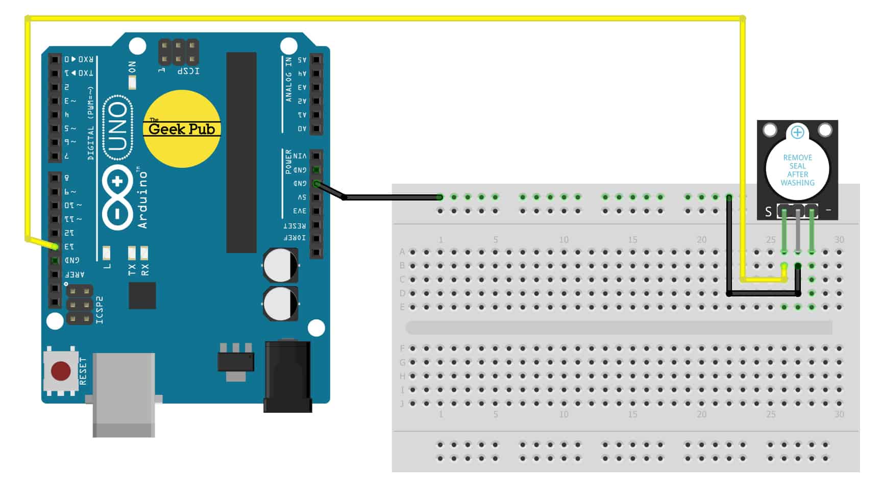
KY-012 Active Buzzer Code Example for Arduino
In this KY-012 active piezo buzzer example code, we’ll simply sound the buzzer for 3 seconds followed by two seconds of silence and then repeat.
Arduino Wiring:
- KY-012 Module GND to Arduino GND
- KY-012 Module Signal to Arduino PIN 13
- KY-012 Module Vcc+ to No Connection
int GPActiveBuzzer = 13;

void setup ()
{
  pinMode (GPActiveBuzzer, OUTPUT); // set pin to output mode
}

void loop () //Main program loop
{
  digitalWrite (GPActiveBuzzer, HIGH); // sound the buzzer
  delay (3000); // pause code for 3 seconds
  digitalWrite (GPActiveBuzzer, LOW); // stop the buzzer
  delay (2000); // pause code for 2 seconds
}
The following code example is for the Raspberry Pi using the Python programming language. This code will beep the buzzer for 3 seconds, followed by 2 seconds of silence.
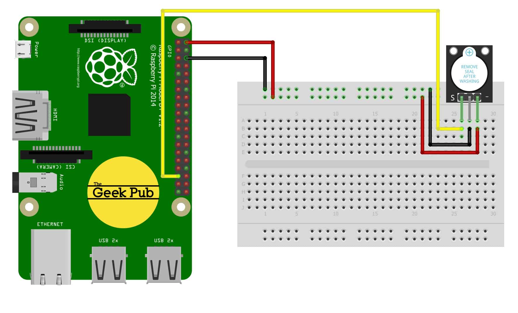
KY-012 ACTIVE BUZZER CODE EXAMPLE FOR RASPBERRY PI
Raspberry Pi Wiring:
- KY-012 Module GND to Raspbery Pi GND
- KY-012 Module Signal to Raspberry Pi PIN 18
- KY-012 Module Vcc+ to Raspberry Pi PIN 1
import RPi.GPIO as GPIO
import time

GPIO.setmode(GPIO.BCM)

# Define the output pin
GPActiveBuzzer = 24
GPIO.setup(GPActiveBuzzer_PIN, GPIO.OUT, initial= GPIO.LOW)

while True:
    GPIO.output(GPActiveBuzzer_PIN,GPIO.HIGH) #Buzzer on
    time.sleep(4) #pause for 4 seconds
    GPIO.output(GPActiveBuzzer_PIN,GPIO.LOW) #Buzzer off
    time.sleep(2) #pause for 2 seconds
We hope this wiki article has been helpful to you. Please leave a comment below if you have any questions or comments, as we try to keep these articles constantly up to date.