Sensor Wiki: KY-006 Passive Piezo-Buzzer Module
This wiki article covers the KY-006 passive piezo-buzzer module. Included are wiring diagrams, code examples, pinouts, and technical data. This sensor is a fantastic sensor for providing simple audible feedback to your projects and can be setup with the absolute minimum of effort.
Content
- Sensor/Module Image Gallery
- Description and Technical Data
- Device Pinout
- Projects that use this Sensor/Module
- Code Examples
- Code example for Arduino
- Code example for Raspberry Pi

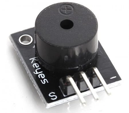
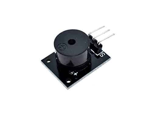
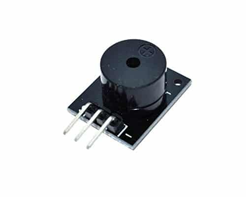
Sensor Module Image Gallery


Description and Technical Data
The KY-006 passive piezo buzzer is a 3-pin module that creates an audible sound of varying frequencies using pulse width modulation (PWM). It can produce a range of tones and sounds depending on the input. Due to this, it is commonly used to create sound effects or simple musical notes for short songs.
Tech Specs for the KY-006 Active Buzzer:
- Min/Max Operating Voltage 1.5V to 15V DC
- Current: <25mA
- Frequency: <20Hz to >2.5kHz
- Dimensions: 0.728in x 0.591in (18.5mm x 15mm)
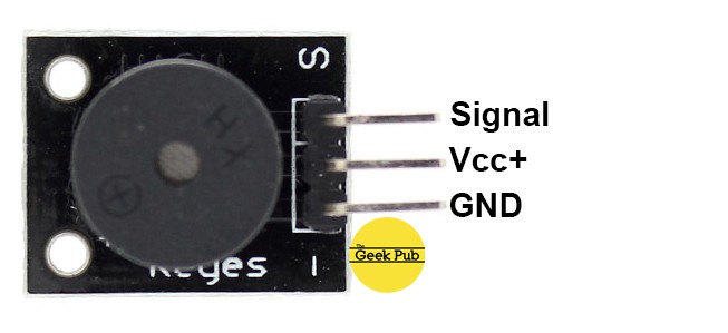
Device Pinout & Schematics
This module has three pins: GND, Vcc+, and Signal.
Our Projects that Use this Sensor
We do not currently have an projects that feature the KY-006, but check back soon!
Code Examples
You’ll find below code examples of using the KY-006 passive piezo buzzer with both Arduino and Raspberry Pi (Python).
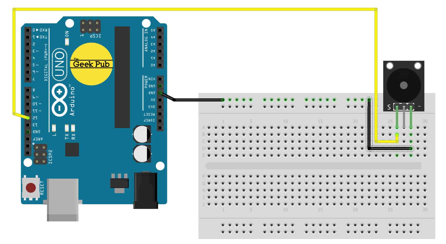
KY-006 Passive Buzzer Code Example for Arduino
In this KY-006 passive piezo buzzer example code, we will create the standard alarm signal example that cycles the sound of the passive buzzer.
Arduino Wiring:
- KY-006 Module GND to Arduino GND
- KY-006 Module Signal to Arduino PIN 12
- KY-006 Module Vcc+ to No Connection
// define the pin we will connect to
int buzzer = 12 ;
void setup ()
{
// set our pin to output mode
pinMode (buzzer, OUTPUT) ;
}
void loop ()
{
// loop through frequencies to generate alarm sound
unsigned char i;
while (1)
{
//Frequency 1
for (i = 0; i <80; i++)
{
digitalWrite (buzzer, HIGH) ;
delay (1) ;
digitalWrite (buzzer, LOW) ;
delay (1) ;
}
//Frequency 2
for (i = 0; i <100; i++)
{
digitalWrite (buzzer, HIGH) ;
delay (2) ;
digitalWrite (buzzer, LOW) ;
delay (2) ;
}
}
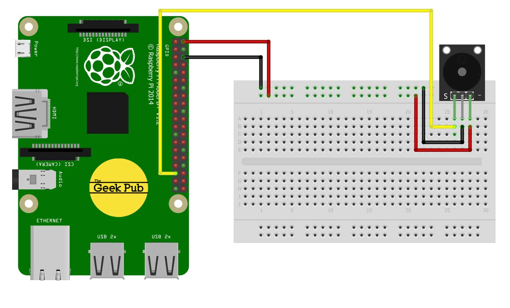
}KY-006 PASSIVE BUZZER CODE EXAMPLE FOR RASPBERRY PI
The following code example is for the Raspberry Pi using the Python programming language. This code will create the classic alarm signal on the buzzer by cycling the tones up and down.
Raspberry Pi Wiring:
- KY-006 Module GND to Raspbery Pi GND
- KY-006 Module Signal to Raspberry Pi PIN 18
- KY-006 Module Vcc+ to Raspberry Pi PIN 1
# import modules
import RPi.GPIO as GPIO
GPIO.setmode(GPIO.BCM)

# define the pin we will attach to
GPIO_PIN = 18
GPIO.setup(GPIO_PIN, GPIO.OUT)

# start at 50 hertz
GPFrequency = 50
pwm = GPIO.PWM(GPIO_PIN, GPFrequency)
pwm.start(50)

    while(True):
    	for GPFrequency in range(5000):
	        pwm.ChangeFrequency(GPFrequency)
We hope this wiki article has been helpful to you. Please leave a comment below if you have any questions or comments, as we try to keep these articles constantly up to date.