Blog
Control High Voltage Devices with an Arduino
One of the best features of the Arduino is the ability to control relays. Relays allow a circuit of one voltage or current to be operated by a circuit of a different voltage or current. In the case of an Arduino that operates at either 3.3V or 5V DC, connecting a relay allows us to operate a device that uses 110V to 240V AC. Simply put, with a relay your Arduino can control your coffee maker, a lamp, or other high voltage devices. In this tutorial we will learn how to control high voltage devices with an Arduino!
Arduino Relay Tutorial for High Voltage Control
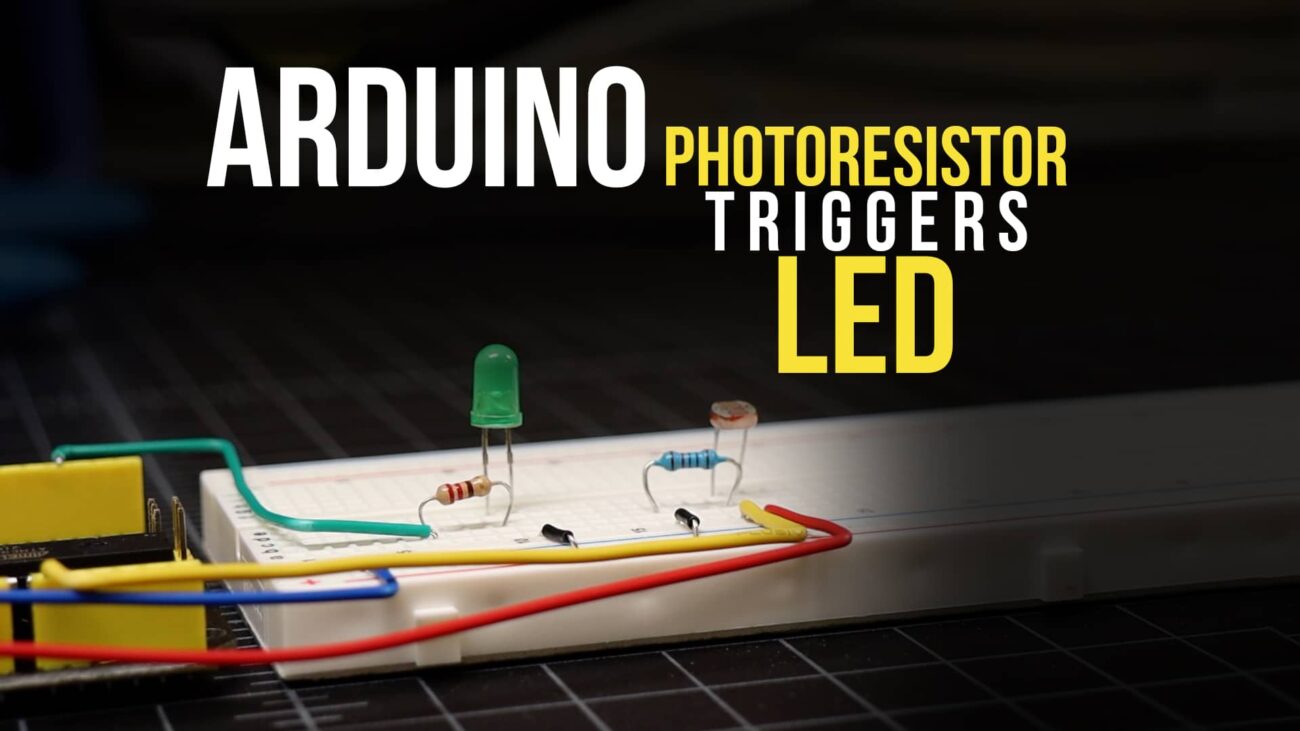
As with most things Arduino, we’re going to need a little code and we’ll need an input. While it’s certainly feasible to do this project without any inputs (using a timer loop, for example), we’re going to use a photoresistor. A photoresistor is a resistor that changes its resistance based on the amount of ambient light reaching its sensor plate. By reading the value of resistance we can make a pretty good guess about the amount light in a room. We’ll use the photoresistor (sometimes called a photocell) to decide whether it is light or dark in the room. If it’s dark, we’ll turn on a relay that will operate a lamp! This of course is an Arduino night light!
Parts List for this Project
In order to do this project you’ll need the following components:
| QTY | PART/LINK | ||
|---|---|---|---|
| 1X | [icon name=”microchip” prefix=”fas”] | Arduino Uno | [icon name=”cart-plus” prefix=”fas”] |
| 1X | [icon name=”usb” prefix=”fab”] | USB Type B Cable | [icon name=”cart-plus” prefix=”fas”] |
| 1X | [icon name=”th” prefix=”fas”] | Solderless Breadboard | [icon name=”cart-plus” prefix=”fas”] |
| 1X | [icon name=”grip-lines” prefix=”fas”] | Jumper Wire Kit | [icon name=”cart-plus” prefix=”fas”] |
| 1X | [icon name=”toggle-off” prefix=”fas”] | Light Sensor / Photoresistor | [icon name=”cart-plus” prefix=”fas”] |
| 1X | [icon name=”ellipsis-h” prefix=”fas”] | Resistor Kit (220 Ohm) | [icon name=”cart-plus” prefix=”fas”] |
| 1X | [icon name=”power-off” prefix=”fas”] | Relay Kit | [icon name=”cart-plus” prefix=”fas”] |
Before you can control high voltage devices with an Arduino, you’re going to need a relay. I chose a simple 5V relay from Amazon that already has pins and screw terminals to make this project easy. Additionally, rather than cutting my lamp cord, I am just going cut an old extension cord in half and use that to connect to my lamp.
Understanding the 5V Relay
As we move forward with our Arduino relay tutorial, let’s take a minute to understand how the relay is designed and the basics of how it works. This will make it easier to understand the fundamentals of our project as we proceed. If you’re already familiar with the basics of a relay feel free to skip on to the next section. However, your relay may not be the same configuration as the one we chose. If yours is different you might need to make some small changes to this project.
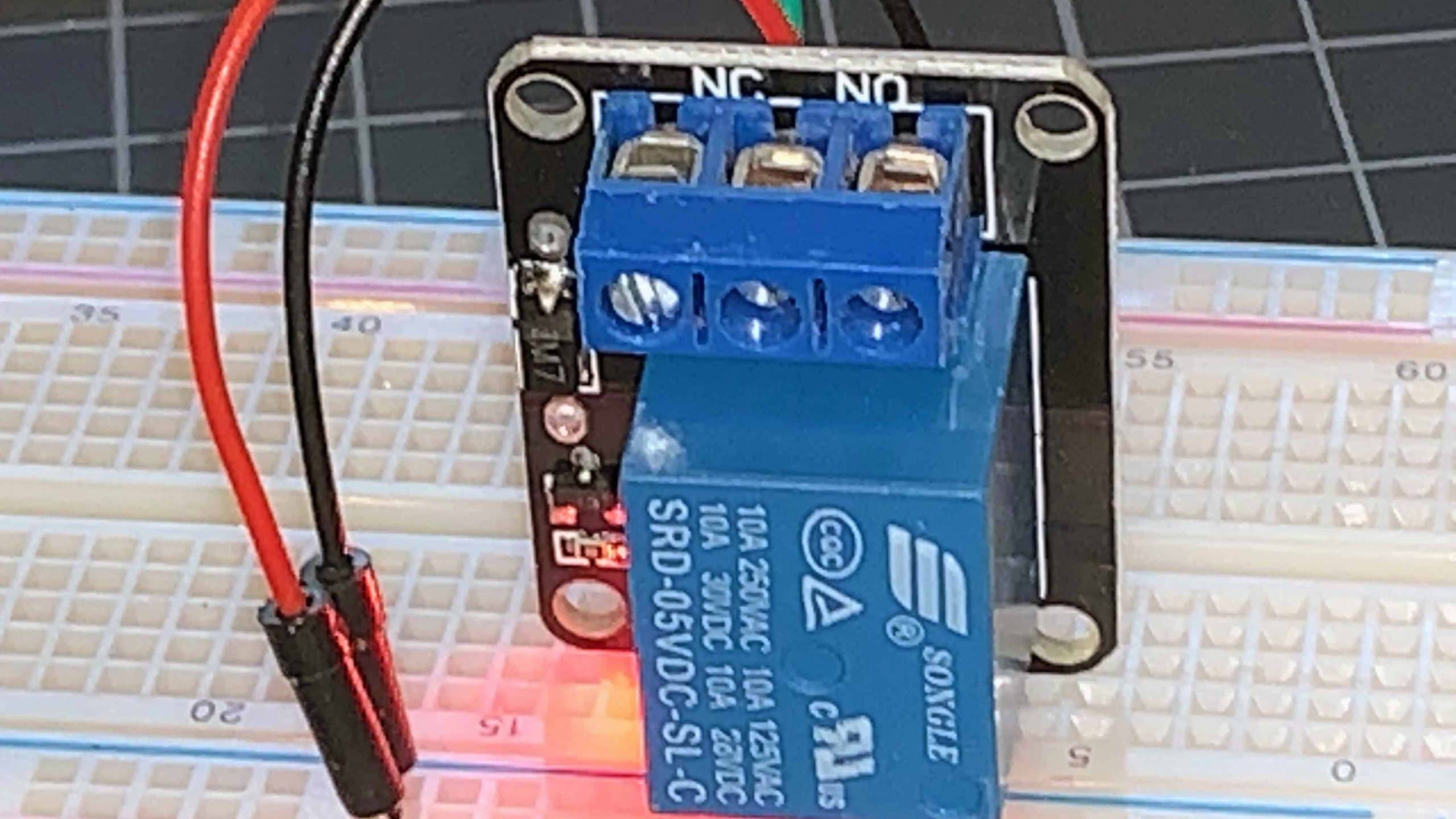
The relay we chose is already mounted on a circuit board, and includes screw terminals. The pins on the board are the low voltage terminals and will connect to your Arduino. The screw terminals are the high voltage side of the relay and these will connect to our lamp. I’ve made a diagram to help you understand the relay pinout a little easier.

On the low voltage side of the relay you’ll see three pins. These should be labeled GND, Vcc, and S. GND is for ground, Vcc is for +5 volts, and S is for signal. On the high voltage side of the relay you’ll have three screw terminals that should be labeled, NC, C, and NO. NC is for normally-closed, NO is for normally-open, and C is for common. Let’s break these down just a little:
- GND is the ground pin.
- Vcc will get +5 volts from the Arduino 5v header pin.
- S or signal will be connected to a digital I/O pin on the Arduino header.
- C or common carries voltage from NO or NC. Do not confuse this terminal with ground!
- NO is the normally-open contact.
- NC is the normally-closed contact.
Normally-Closed vs. Normally Open Contacts
You might be thinking “What is NC and NO?” What’s the difference?” This is a very common questions those new to relays first ask. Normally-open and normally closed are the two main pins most relays will have. With normally-open, the switch is off until signal pin is activated. With normally-closed the switch is off until the signal pin is activated. Which one you use depends on how you wire your project and what behavior you wish it to have.
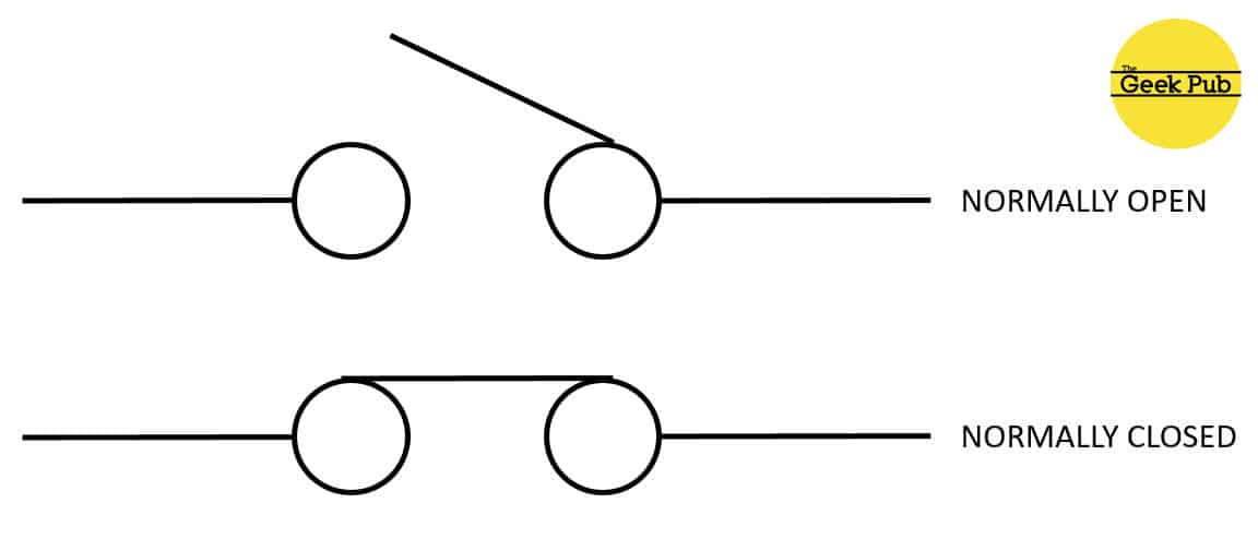
In our project we will wire to the normally-open pin so that the lamp will stay off until we apply +5v to the signal pin. Of course, you could wire it the opposite way and simply change the Arduino code to work backwards. I prefer this configuration because its the fail-safe mode. In this configuration should the Arduino lose power, the lamp will not be stuck on, but rather stuck off.
Controlling a Relay with a Photoresistor
The first thing we need to do is wire everything up. This is of course where I have to break out my safety cap and make sure you understand the following:
[box type=”warning”] WARNING: This project deals with 100v to 240v AC “mains” voltage. Make sure you understand the danger involved with this project and take precautions to avoid electrocution which could kill you or cause permanent damage. If you’re not sure, seek help or skip this project! [/box]
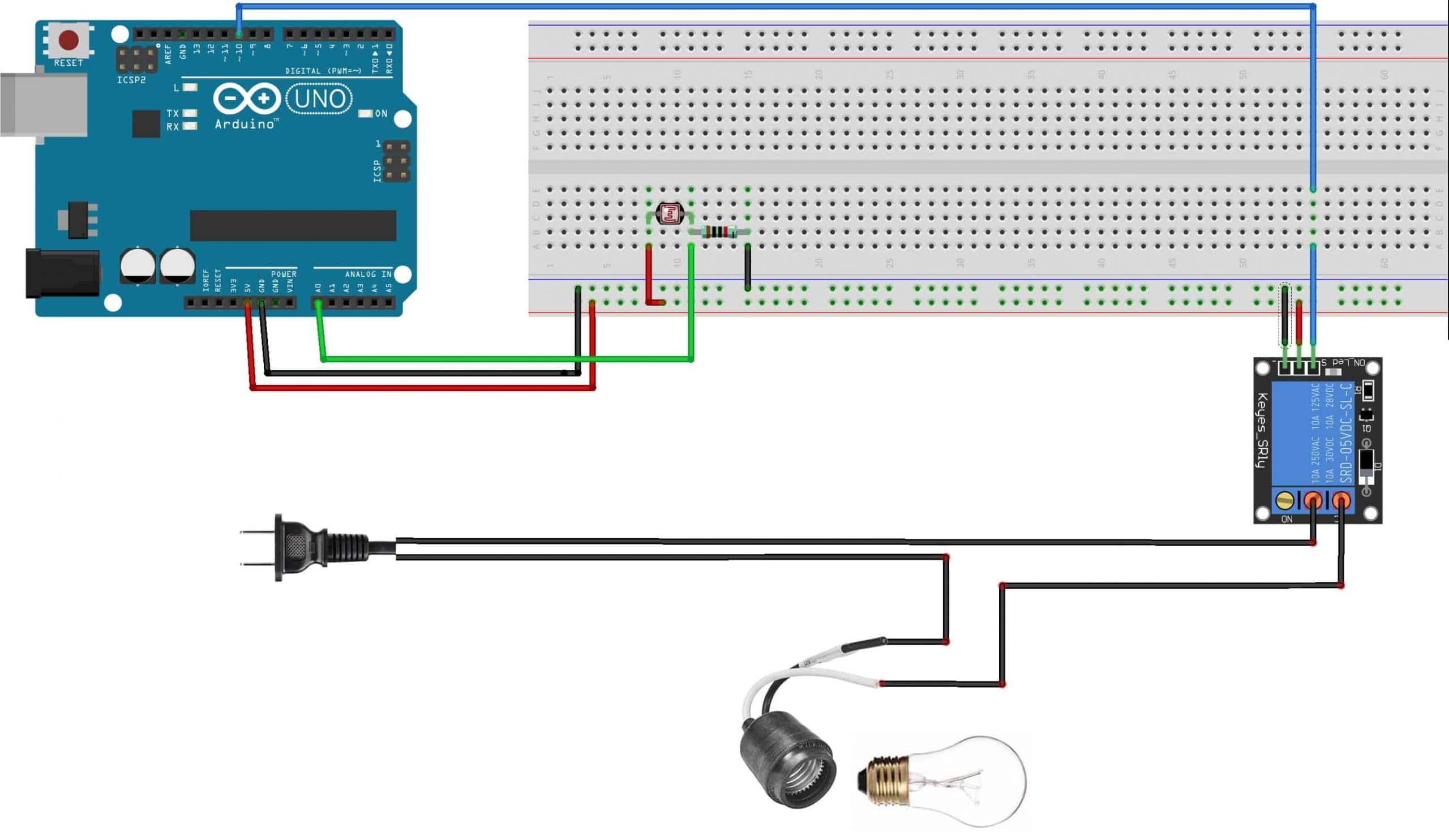
Although in this Arduino “night light” diagram we’ve shown the lamp wire spliced and connected, I would actually recommend you do this to an extension cord so as not to permanently damage the cord on your lamp. This also allows you to switch out the lamp at a later time without rewiring anything.
Another thing I highly recommend is to put all of this into a project box as to protect the exposed high-voltage terminals and wires from accidentally making contact with humans or pets in your home. Just drill a hole in the box for the photoresistor to pass through to the outside.
The Arduino Relay Control by Photoresistor Code
Next, let’s drop the following incredibly basic code into the Arduino IDE and upload it to your Arduino.
/*
* The Geek Pub Sample Code
* Control a Relay with an Arduino and Photoresistor
* Freely distributable with attribution.
*/

//Constants
const int pResistor = A0; // Photoresistor at Arduino analog pin A0
const int relayPin=10; // Led pin at Arduino pin 9

//Variables
int prvalue; // Store value from photoresistor (0-1023)

void setup(){
  pinMode(relayPin, OUTPUT); // Set lepPin - 9 pin as an output
  pinMode(pResistor, INPUT); // Set pResistor - A0 pin as an input
  Serial.begin(9600);
  }

void loop(){
  prvalue = analogRead(pResistor);
  Serial.print("PR Value: ");
  Serial.println(prvalue);

  // edit value depending on your photoresistor specs
  if (prvalue < 350){
    digitalWrite(relayPin, HIGH); // Activate Relay (lamp on)
    }
  else{
    digitalWrite(relayPin, LOW); // Deactivate Relay (lamp off)
    }

  delay(1000); //Small delay
}
The code is very simply. It simply looks for a value on the analog 0 pin and stores that into an integer. We look for a value of higher or lower than 350 and make the decision to set digital pin 10 to HIGH or LOW. This of course changes the state of the normally closed pin accordingly.
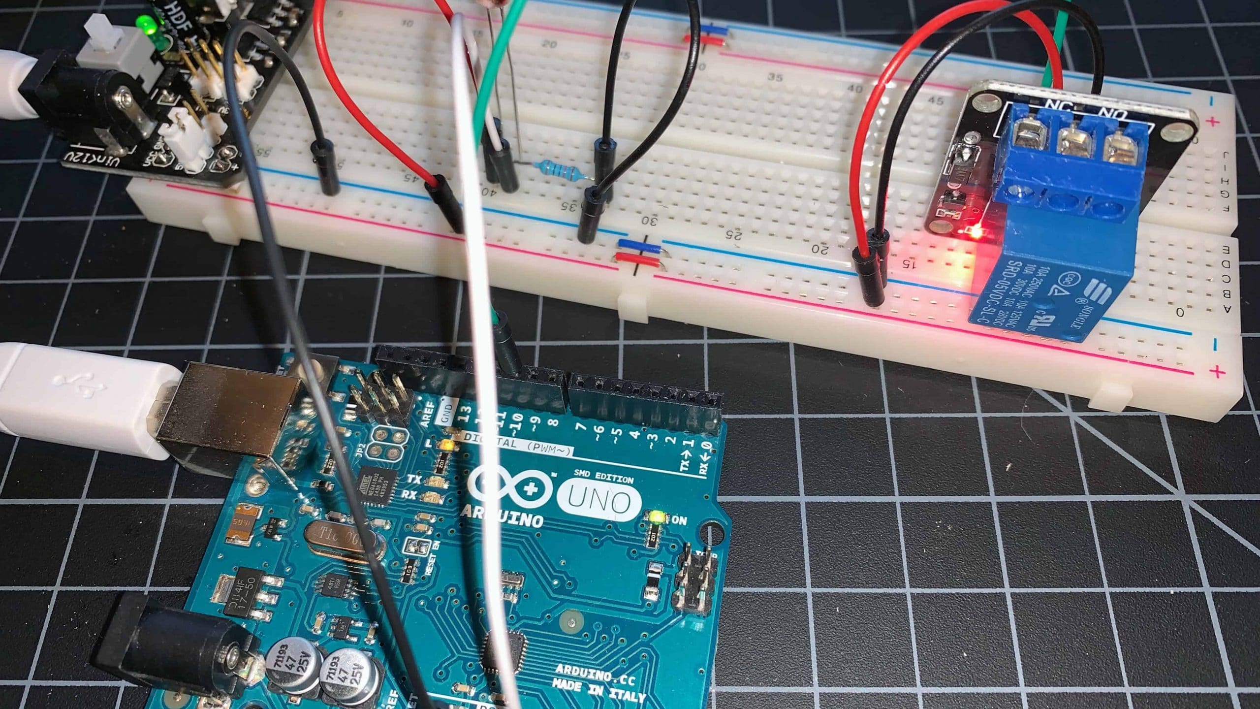
And here is the relay in action. Blocking light from the photoresistor will activate the relay! That’s all there is to this project!
Some of you will undoubtedly suggest that instead of an extension cord, this could be accomplished with an outlet box, and that is absolutely true. One word of caution is the size your relay appropriately. In our case this relay is only capable of 10 amps maximum current. That’s fine for a lamp, but most wall sockets are rated at 15 amps. If you plug something like a space heater into the socket you’ll fry your relay and risk a fire.
Feel free to leave a comment below with how you’re using this project, or ask any questions you might have! We’ll do our best to answer them for you.
Next Steps
Now you can go on to the next tutorial or go back to the index!


5
Absolutely fantastic. Thank you! I setup an LED star wars light in my son’s room that turns on to wake him up every morning. I put the Arduino inside the lamp and drilled a small hole to expose the photoresistor and then hot glued it in place. Love what you’re doing here.
4.5