Blog
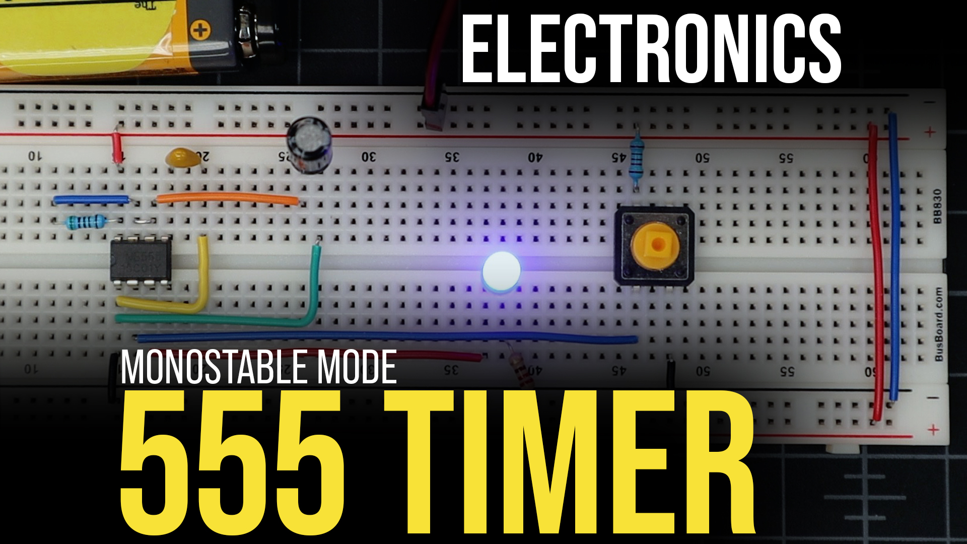
Using a 555 Timer in Monostable Mode
In this tutorial we’re going to learn about using a 555 timer in monostable mode, but first a little history is in order! Without a doubt the 555 timer is one of the most common, if not the most common integrated circuits used on electronics over the last 45+ years. First entering production in 1971 it has been used in an enormous amount of DIY projects and even commercial products that include computers such as the Commodore 64 (and many others).
In modern commercial products the 555 timer is mostly obsolete, replaced SoC (or System on a Chip) designs, where the functionality of the 555 timer is simply integrated into other chips. This reduces the number of components on a board and makes the overall product less expensive. However, the 55 timer finds its way into many hobby projects because of its simplicity and affordability. You can buy one-hundred 555 timers eBay or Amazon for about $5.
What is a 555 Timer?
The 555 is called a timer, or “555 timer”. This is because it can pulse electrical currents for an exact amount of time based on the the values of resistors and capacitors connected to the timer. The timer has three modes of operation:
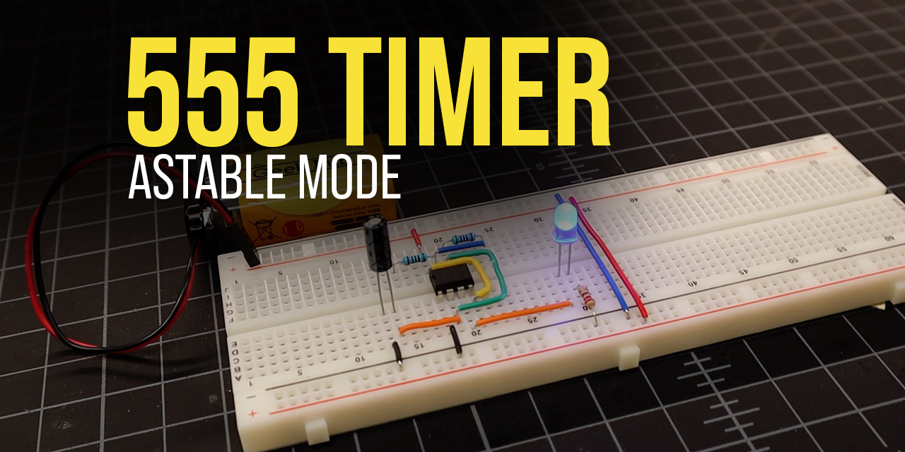
- Astable – This the most commonly used mode of the 555 timer. It cycles a repeating pulse of current for a specific amount of time. If you’ve ever seen a product that has some component that operates on a repeating cycle such as a flashing LED, there is a good chance that there is a 555 timer operating in astable mode behind the scenes.
- Monostable – In this mode, the 555 timer outputs a pulse of current for a specific amount of time and then stops. We’ll use this in our example below to to turn on an LED for short period of time after a button has been pressed.
- Bistable – This mode of the 555 timer is different that the other two in that it does not use a capacitor or resistor to set a timing pulse, rather inputs from the trigger and reset pins control its states.
Watch the 555 Timer Monostable Mode Video
Parts List for this Project
Here’s a quick parts list to get you going quickly on building this project:
| QTY | PART/LINK | ||
|---|---|---|---|
| 1X | [icon name=”microchip” prefix=”fas”] | 555 Timer IC | [icon name=”cart-plus” prefix=”fas”] |
| 1X | [icon name=”th” prefix=”fas”] | Solderless Breadboard | [icon name=”cart-plus” prefix=”fas”] |
| 1X | [icon name=”grip-lines” prefix=”fas”] | Jumper Wire Kit | [icon name=”cart-plus” prefix=”fas”] |
| 1X | [icon name=”ellipsis-h” prefix=”fas”] | Resistor Kit (330/5.1K/10K Ohm) | [icon name=”cart-plus” prefix=”fas”] |
| 1X | [icon name=”lightbulb” prefix=”fas”] | LED Kit | [icon name=”cart-plus” prefix=”fas”] |
| 1X | [icon name=”circle” prefix=”fas”] | Electrolytic Capacitor Kit (470 μF) | [icon name=”cart-plus” prefix=”fas”] |
| [icon name=”circle” prefix=”fas”] | Ceramic Capacitor Kit (10 pf) | [icon name=”cart-plus” prefix=”fas”] | |
| 1X | [icon name=”toggle-on” prefix=”fas”] | Button Kit | [icon name=”cart-plus” prefix=”fas”] |
| 1x | [icon name=”battery-full” prefix=”fas”] | 9V Battery | [icon name=”cart-plus” prefix=”fas”] |
| 1x | [icon name=”pause-circle” prefix=”fas”] | 9V Battery Snap for Breadboard | [icon name=”cart-plus” prefix=”fas”] |
Some of these links may be affiliate links. If you use them, they cost you nothing, but we may get a small commission that helps us keep making great content like this.
555 Timer in Monostable Mode Example
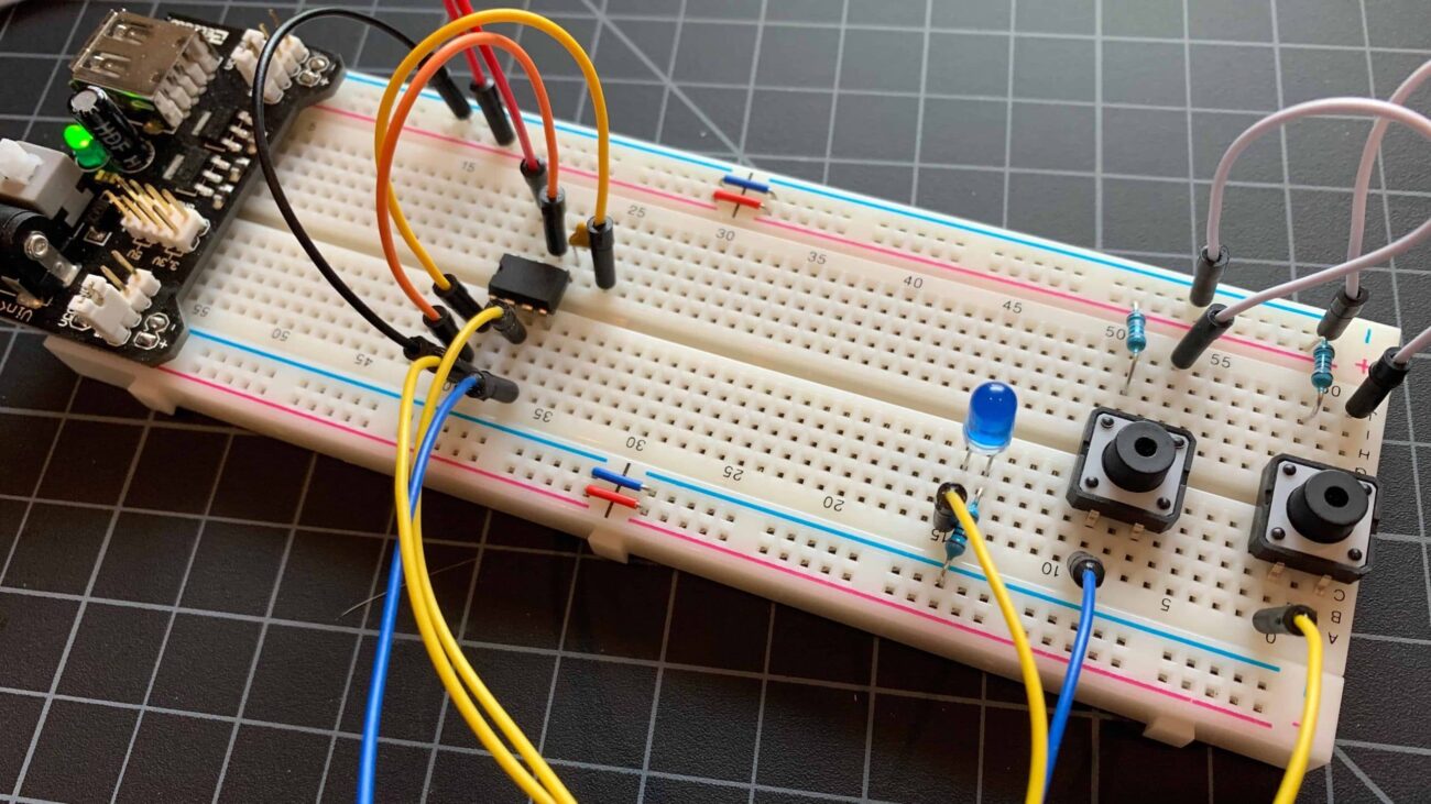
So let’s build an example of using a 555 Timer in monostable mode. You’ll only need a few components for this and it is very simple to wire up. In this example we will have a push button activate the timer. The timer will keep the LED on for short period of time (~5 seconds) and then turn it back off.
Wiring the 555 Timer for Monostable Mode
Use the following diagram to wire the 555 timer for monostable mode. If you don’t have the exact values for the resistor and electrolytic capacitor connected to PIN 1 and PIN 3 of the 555 timer, that’s OK. You can experiment with different values and it will change how long the LED stays lit after pressing the button. In fact, if you have a potentiometer, you could use it in place of the resistor to make your timing adjustable!

555 Timer Monostable Pinout
The following reference should help you understand the wiring concepts of a 555 timer.

- PIN 1 – Connected to ground (GND / Vcc-)
- PIN 2 – When voltage drops below 1/3 of Vcc+ the trigger is activated.
- PIN 3 – Outputs up to 200 mA of current at ~1.5 volts.
- PIN 4 – When connected to ground resets the timing operation of the output.
- PIN 5 – Connected to ground via a 10 pF capacitor to prevent fluctuations in timing of the RC circuit. (Normally, control, but not used in Monostable mode).
- PIN 6 – Turns off the output when the voltage supplied to it reaches above 2/3 Vcc. Referred to as the threshold.
- PIN 7 – When output voltage is low, it discharges the capacitor.
- PIN 8 – Vcc+ Vonnected to the + side of the 9V battery (You can actually use any voltage between 4.5V and 15V to power the 555 in case you’re using a benchtop power supply).
While everything is at idle, the voltage at the trigger pin will be HIGH. In this configuration, the discharge pin allows current to flow to ground (GND) and prevents the capacitor from from building a charge.
Pressing the button causes the voltage at the trigger pin to go LOW, causing the output pin to become active. The discharge pin will stop the flow of current from the capacitor to ground (GND). This will cause the capacitor to begin accumulating a charge.
When the capacitor reaches levels become two-thirds of the input voltage, the output pin is switched off and the discharge pin returns flow to ground (GND). This effectively resets the entire circuit, now waiting for the next button press. The time it takes to charge the electrolytic capacitor is what determines how long the LED will stay lit. This is why changing the resistor value or capacitor value will change the circuit timing.
Using a 555 Timer in Monostable Mode: The Results
Once you get everything wired up correctly, your results should look like the following GIF image. Press the button, and the blue LED will light for approximately 5 seconds and turn off. You can repeat this cycle over and over!
RELATED: 555 Timers in Astable Mode – Blink an LED Automatically
That wraps up this tutorial on using a 555 Timer in monostable mode. If you have any questions or need some help, leave a comment below and our community will do our best to help you out!
4.5