In this project we’re going to put together a simple Arduino train crossing! While practically this project is simply to help you learn how to use buttons, LEDs, and servos in your Arduino project, this train crossing (also called a level crossing) project could be adapted to model train sets with very little work. In fact, one Arduino could control numerous train crossings (even more with an Arduino Mega)!
If you’d like to make this project here’s a simple parts list to get you started:
Optional Components:
Optionally, you could buy a 200 piece Arduino starter kit! It has a lot more than you need, but it is very affordable and opens the door to many other projects.
RELATED: Our Picks for the Best Arduino Starter Kits
Building the Arduino train crossing project is a lot of fun and can teach kids (and adults the like) the power of a micro-controller. The entire world around you is run by micro-controllers and small form factor computers. When you realize this (if you’re like me), you start to realize all of the practical real world applications and the power of the Arduino platform.
RELATED PROJECT: Arduino Traffic Light Project
Our Arduino train crossing doesn’t 100% emulate a real crossing guard, but the code could easily be modified to do so. The main differences are as follow:
The entire code for this project will be listed below, but first let’s go through each of the major sections to help you understand them in principle.
These functions are simple mostly because they rely on the servo.h library that is built into the Arduino IDE. What might be confusing are the numbers that follow as they are not obvious. By default, most servos are zero to 180 degrees in movement. However, in our train crossing we are only moving them about 80 degrees (because real train crossings only open that far). This means the left train crossing servo will move from the 180 degree position to the 90 degree position, while the right will operate from the 0 degree position to the 80 position.
void CrossingGuardsDown() {
  // Bring the Crossing Guard arms to the down state
  myServo1.write(180);
  myServo2.write(0);
}

void CrossingGuardsUp() {
  // Bring the Crossing Guard arms to the up state
  myServo1.write(90);
  myServo2.write(80);
}
The FlashLEDs function does exactly what you’d expect. It flashes the LEDs on the Arduino train crossing in the pattern and order that matches an authentic crossing guard. It accepts three variables: flashTimes, flashDelay, and beep.
The final section of this code will of course set the state of all LEDs back to off.
void FlashLEDs(int flashTimes, int flashDelay, bool beep) {
  // Flash the crossing guard warning indicators for xx period of time
  int ctr1 = 0;
  for (ctr1 = 0; ctr1 <= flashTimes; ctr1 += 1) {
    // Outer lights on, inner lights off
    digitalWrite(ledPin1L, HIGH);
    digitalWrite(ledPin2R, HIGH);
    digitalWrite(ledPin2L, LOW);
    digitalWrite(ledPin1R, LOW);

    // if beep is true buzz the buzzer only on this cycle
    if (beep == true) {
      digitalWrite(buzzerPin, HIGH);
    }
    delay(flashDelay);
    // if beep is true stop the buzzer
    if (beep == true) {
      digitalWrite(buzzerPin, LOW);
    }
    // Inner lights on, outer lights off
    digitalWrite(ledPin2L, HIGH);
    digitalWrite(ledPin1R, HIGH);
    digitalWrite(ledPin1L, LOW);
    digitalWrite(ledPin2R, LOW);
    delay(flashDelay);
  }
  // all lights off at end of sequence
  digitalWrite(ledPin1L, LOW);
  digitalWrite(ledPin2R, LOW);
  digitalWrite(ledPin2L, LOW);
  digitalWrite(ledPin1R, LOW);
}
The setup for this function is all about setting the pinModes for each LED, the buzzer, and attaching the servos using the servo library. I also configure the serial console at 9600 baud so we can dump messages back to our PC for troubleshooting purposes.
void setup() {
  // initialize the pushbutton pin as an input:
  pinMode(buttonPin, INPUT);

  // initialize the LED pins as an output:
  pinMode(ledPin1L, OUTPUT);
  pinMode(ledPin1R, OUTPUT);
  pinMode(ledPin2L, OUTPUT);
  pinMode(ledPin2R, OUTPUT);

  // initialize the servo pins
  myServo1.attach(servo1Pin);
  myServo2.attach(servo2Pin);

  // set inital crossing guard positions
 CrossingGuardsUp();

  // initialize the buzzer pin as output:
  pinMode(buzzerPin, OUTPUT);

  // write to the serial console that we're up!
  Serial.begin(9600);
  Serial.println("Train Crossing Active!");
}
The loop function is very simplistic, even though it looks a little complicated. All it does is look for a press of the button and then run a set of flashes and servo operations.
void loop() {
  // read the state of the pushbutton value:
  buttonState = digitalRead(buttonPin);

  // check if the pushbutton is pressed. If it is, the buttonState is HIGH:
  if (buttonState == HIGH) {
    // start the crossing guard actions

    // Write console notifications
    Serial.println("Train Crossing Button Pressed!");

    // flash the LEDs x number of times for YY milliseconds
    FlashLEDs(7, 200, true);

    // lower the crossing guards
    CrossingGuardsDown();

    // flash the LEDs x number of times for YY milliseconds
    FlashLEDs(20, 200, true);

    // open the crossing guards when complete
    CrossingGuardsUp();

    // flash the LEDs x number of times for YY milliseconds
    FlashLEDs(5, 200, false);
  }
}
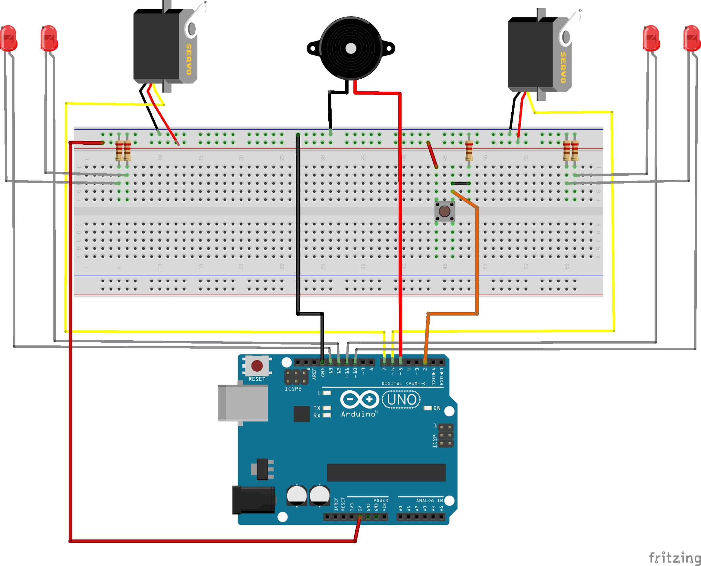
The following schematic is for wiring the crossing guard. Although for simplicity sake I’ve shown the servo’s powered by the Arduino directly, it is highly recommended you power them from a separate power source. If you run into issues with things acting funny, or the servos not moving correctly, this fix is almost definitely to move them to a dedicated power source. You can add an Arduino power module to your breadboard with one of these.
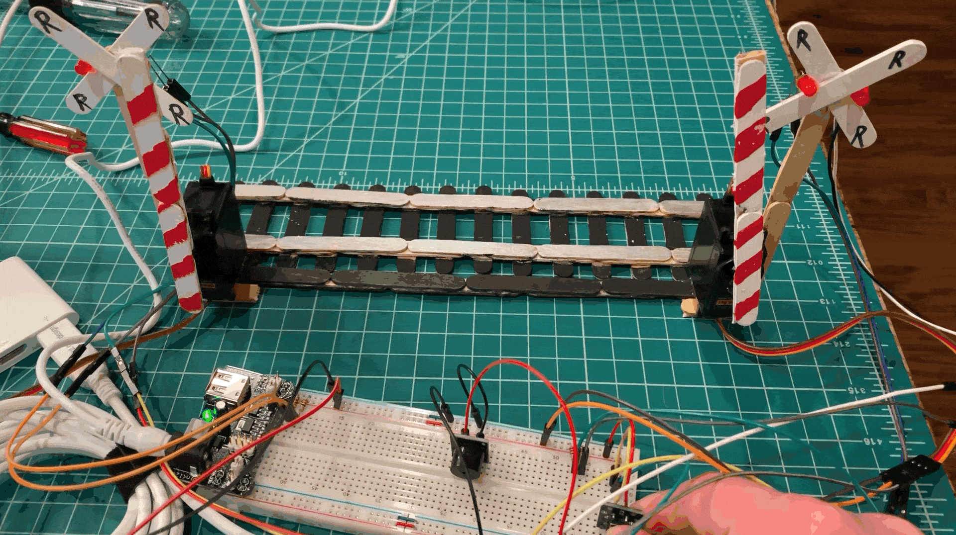
Here are some final pictures of the Arduino train crossing project made from Popsicle sticks as a proof of concept. What a fun project this one was and the kids just loved it!


Here’s the complete code for the Arduino sketch that you can copy and paste into your IDE.
// Train crossing ©The Geek Pub, LLC - Mike Murray 2019
// Freely distributable with attribution and link to TheGeekPub.com

#include <Servo.h>

//Let's define easy constants for the components so we can remember them easier
const int buttonPin = 2; // the number of the pushbutton pin
const int ledPin1L = 13; // the number of the 1st Indicator LED Left pin
const int ledPin1R = 12; // the number of the 1st Indicator LED Right pin
const int ledPin2L = 11; // the number of the 2nd Indicator LED Left pin
const int ledPin2R = 10; // the number of the 2nd Indicator LED Right pin
const int servo1Pin = 7; // the number of the 1st Crossing Guard Servo pin
const int servo2Pin = 6; // the number of the 2nd Crossong Guard Servo pin
const int buzzerPin = 5; // the number of the buzzer pin (optional)

// variables will change:
int buttonState = LOW; // variable for reading the pushbutton status

// create servo objects
Servo myServo1;
Servo myServo2;

void setup() {
  // initialize the pushbutton pin as an input:
  pinMode(buttonPin, INPUT);

  // initialize the LED pins as an output:
  pinMode(ledPin1L, OUTPUT);
  pinMode(ledPin1R, OUTPUT);
  pinMode(ledPin2L, OUTPUT);
  pinMode(ledPin2R, OUTPUT);

  // initialize the servo pins
  myServo1.attach(servo1Pin);
  myServo2.attach(servo2Pin);

  // set inital crossing guard positions
  CrossingGuardsUp();

  // initialize the buzzer pin as output:
  pinMode(buzzerPin, OUTPUT);

  // write to the serial console that we're up!
  Serial.begin(9600);
  Serial.println("Train Crossing Active!");
}

void CrossingGuardsDown(){
  // Bring the Crossing Guard arms to the down state
  myServo1.write(180);
  myServo2.write(0);
}

void CrossingGuardsUp(){
  // Bring the Crossing Guard arms to the up state
  myServo1.write(90);
  myServo2.write(80);
}

void FlashLEDs(int flashTimes, int flashDelay, bool beep) {
  // Flash the crossing guard warning indicators for xx period of time
  int ctr1 = 0;
  for (ctr1 = 0; ctr1 <= flashTimes; ctr1 += 1) {
  // Outer lights on, inner lights off
  digitalWrite(ledPin1L, HIGH);
  digitalWrite(ledPin2R, HIGH);
  digitalWrite(ledPin2L, LOW);
  digitalWrite(ledPin1R, LOW);

  // if beep is true buzz the buzzer only on this cycle
  if (beep == true) {
    digitalWrite(buzzerPin, HIGH);
  }
  delay(flashDelay);
  // if beep is true stop the buzzer
  if (beep == true) {
    digitalWrite(buzzerPin, LOW);
  }
  // Inner lights on, outer lights off
  digitalWrite(ledPin2L, HIGH);
  digitalWrite(ledPin1R, HIGH);
  digitalWrite(ledPin1L, LOW);
  digitalWrite(ledPin2R, LOW);
  delay(flashDelay);
  }
  // all lights off at end of sequence
  digitalWrite(ledPin1L, LOW);
  digitalWrite(ledPin2R, LOW);
  digitalWrite(ledPin2L, LOW);
  digitalWrite(ledPin1R, LOW);
}

void loop() {
  // read the state of the pushbutton value:
  buttonState = digitalRead(buttonPin);

  // check if the pushbutton is pressed. If it is, the buttonState is HIGH:
  if (buttonState == HIGH) {
    // start the crossing guard actions

    // Write console notifications
    Serial.println("Train Crossing Button Pressed!");

    // flash the LEDs x number of times for YY milliseconds
    FlashLEDs(7, 200, true);

    // lower the crossing guards
    CrossingGuardsDown();

    // flash the LEDs x number of times for YY milliseconds
    FlashLEDs(20, 200, true);

    // open the crossing guards when complete
    CrossingGuardsUp();

    // flash the LEDs x number of times for YY milliseconds
    FlashLEDs(5, 200, false);

    } else {
    // literally do nothing, though you could do some stuff here if you wanted....
    // which is why I put the else here... otherwise just omit the else completely...
  }
}
Be sure to leave a comment below letting us know how your crossing guards worked out!
5 Responses
1
Hey there Mike. I haven’t tried this sketch yet, but I think this is what I’ve been looking for. I belong to a local model railroading club and have been experimenting with Arduinos to animate some things on the club layout. I’m very new to Arduino and using the IDE but have had some success by following examples found on the Web. Specifically, using a servo to switch a turnout with a micro switch to turn on either a red or green LED, depending on the position of the turnout. This was done using one normally open momentary button. First press sets servo to one position, second press returns it to beginning position. Simple. All I had to do was to change the entries in the code to match the position I needed the servo to go to. Next step will be how to add more servos and buttons and how to change the code.
My question on your Train Crossing Project is this: can a sensor to see the train approaching be added to where the push button is? What kind of sensor would I need? What would have to be added to the code to make this work? I’m sure all these are very rudimentary questions for someone who is proficient with computer language, but unfortunately, this is not me. At least not yet. I’m trying to teach myself how to use IDE and I understand some of it but it is a work in progress. I have joined The Geek Pub specifically to learn more about how to use arduino with the model railroading hobby. Any help you could give me would be greatly appreciated. Thank you in advance!
Ken
4.5
Mike Im having trouble getting the code to work, it has an error message by Servo myservo2; can you help?
0.5